Switch and jumper quick reference, Installing the software and drivers – Linx Technologies MDEV-LICAL-MT User Manual
Page 7
–
–
–
–
8
9
Switch and Jumper Quick Reference
• SW1 – This switch activates power to the board.
• SW2 – This switch pulls the ENC_SEL line high so that the transcoder
can be used as an encoder only (positioned down) or operated with
button S9 (positioned up).
• SW3 – Labeled LATCH, this switch is connected to the LATCH line on
the transcoder. If the switch is positioned down, then the status line
outputs are momentary. If it is positioned up, then the status line outputs
follow the Latch Mask (all outputs latched unless changed through the
Serial Interface Engine).
• SW4 – Labeled SEL_BAUD, this switch sets the baud rate of the
transcoder to either 9,600bps (positioned down) or 28,800bps
(positioned up).
• SW5 – Labeled PDN, this switch connects the TR_PDN line on the
transcoder to either the PDN line of the transceiver (positioned to the
right) or to the prototyping header (positioned to the left).
• SW6 – Labeled TR_SEL, this switch connects the TR_SEL line on the
transcoder to either the T/R_SEL line on the transceiver (positioned to
the right) or to the prototyping header (positioned to the left).
• SW7 – Labeled DATA, this switch connects the TR_DATA line on the
transcoder to either the DATA line on the transceiver (positioned to the
right) or to the prototyping header (positioned to the left).
• S0–S7 – These buttons are connected to the status lines on the
transcoder
• S8 – This button is connected to the CRT/LRN line on the transcoder
• S9 – This button is connected to the ENC_SEL line on the transcoder
• J3 – This is a wire wrap header for use with the prototyping header.
Labels next to the header indicate which transcoder lines are connected
to which pins.
• J4 and J5 – These headers are for use with jumpers to connect the
USB module to the transcoder when using the Serial Interface Engine
with the included software. If the board is to be used manually, then the
jumpers should be removed as the USB interface section will hold the
lines in specific states.
Installing the Software and Drivers
The first time a QS module is plugged into a computer, Windows displays
the Found New Hardware Wizard, which guides the installation of the
drivers. The drivers are included on the CD, so point the wizard to the CD
when prompted. The drivers have not gone through Microsoft’s verification
process, so a message may appear warning of this. Click “Continue
Anyway” to finish the installation process.
Application Note AN-00201 (Installing the SDM-USB-QS-S Drivers)
describes the installation of the drivers in detail. The drivers should be
installed before running the Development Software.
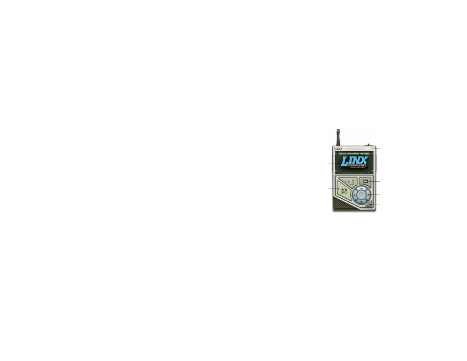
The MT Series Master Development System Software Installer automatically
starts when the CD is inserted and the player in the figure below appears.
The View Documentation button shows a list of the application notes and
manuals related to the MT Series. Selecting one of these opens the file in
Adobe Acrobat. The Play Movie button plays a short video about Linx in the
Player Screen, which can be controlled with the Selection Keypad. Clicking
the button on the bottom right of the player opens the Linx Technologies
homepage in the computer’s default browser.
The View Documentation list also allows for the installation of Adobe
Acrobat Reader, so that the documents may be viewed, and Flash, which
may be required if the Linx video does not play correctly.
Clicking the Install Software button starts the Installation Wizard, which
guides the installation of the development software. The installer places the
software application, MT Series documentation, and USB drivers at the
installed location on the computer's hard drive.
Install Software
View Documentation
Play Movie
Exit
Go to the
Linx Website
Selection Keypad
Player Screen
Figure 8: Software Installer