The decoder board – Linx Technologies MDEV-LICAL-MS User Manual
Page 7
–
–
–
–
8
9
The Encoder Board RF Area
Figure 7 shows the RF area of the development board.
This board can be populated with either the LR Series transmitter (as
shown) or the ES Series transmitter. The LR Series transmitter is placed
on the right side and the ANT1 connector is populated. The ES Series
transmitter is placed on the left and the ANT2 connector is populated.
R27 is connected to the LADJ line of the LR transmitter to reduce the
output power to approximately 0dBm. The LR Series transmitter is capable
of producing more output power than may be legally acceptable, so by
reducing the output power, the range experienced with the evaluation kit
more closely resembles the rage that can be achieved with a final certified
product.
Figure 7: The Encoder Board RF Area
The Decoder Board
The decoder board has three main sections of interest: the decoder area,
the receiver area, and the USB area.
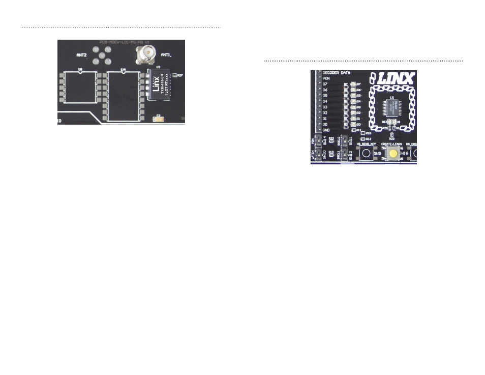
The Decoder Area
Figure 8 shows the decoder area of the development board.
The decoder is placed in the center beneath the Linx logo. To the left are
LEDs that are connected to the decoder data lines. These light up when
the decoder receives a signal from the encoder to take the data line high.
LED D0 corresponds to data line D0 and so forth.
Beneath the decoder are two LEDs. D12 is connected to the MODE_IND
line and lights up as described in the MS Series Decoder Data Guide. D8 is
connected to the RX_CNTL line and provides visual feedback by lighting up
when the decoder activates the receiver when in RX Control Mode.
Beneath the LEDs is a button that is connected to the LEARN line. This
button is used to learn the Address from the encoder as described in the
MS Series Decoder Data Guide.
There are four function switches to the left of the CREATE button. BSEL0
and BSEL1 are used to set the baud rate of the decoder as described in
Figure 6.
Figure 8: The Decoder Area