Power supply guidelines, Pad layout, Helpful application notes from linx – Linx Technologies SDM-USB-QS-S User Manual
Page 8
– –
– –
10
11
Helpful Application Notes from Linx
It is not the intention of this manual to address in depth many of the issues
that should be considered to ensure that the modules function correctly
and deliver the maximum possible performance. We recommend reading
the application notes listed in Figure 11 which address in depth key areas
of RF design and application of Linx products. These applications notes are
available online at www.linxtechnologies.com or by contacting Linx.
Power Supply Guidelines
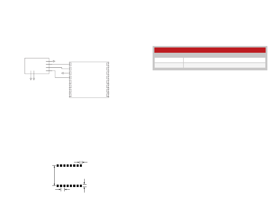
The USB module can be powered in two ways: from the USB bus or from
an external source. If necessary, a voltage regulator can be used to supply
a clean 5V as the external source, or the V
CC
pin can be connected to the
bus power pin of the USB connector. Using the bus to power the module
is an advantage because the module then uses power from the host
rather than from the peripheral. This is especially helpful if the peripheral is
battery-powered. Figure 9 shows the schematic powering from the bus.
The USB specification has strict allowances for using power from the bus.
A device is allowed to use 100mA before enumeration, 500mA during
normal operation, and 500mA in suspend mode. A descriptor stored in the
EEPROM tells the host how much current the device will pull from the bus
so that the host can allocate the appropriate power. The modules come
programmed for 100mA, but if the final product draws more than this, then
the device descriptors need to be changed.
Pad Layout
The following pad layout diagram is designed to facilitate both hand
and automated assembly.
USBDP
USBDM
GND
DSR
DATA_IN
DATA_OUT
RTS
CTS
DTR
TX_IND
VCC
SUSP_IND
RX_IND
485_TX
RI
DCD
1
2
3
4
5
6
7
8
9
10
11
12
13
14
15
16
USB Type B
Connector
GND
5V
DAT -
DAT+
GND
GS
HD
GS
HD
GND
GND
1
2
3
4
5
6
GND
SDM-USB-QS-S
Figure 9: USB Bus-Powered Schematic
0.100"
0.070"
0.065"
0.610"
Helpful Application Note Titles
Note Number
Note Title
AN-00200
SDM-USB-QS-S Programmer's Guide
AN-00201
Installing the SDM-USB-QS-S Drivers
Figure 11: Helpful Application Note Titles
Figure 10: Recommended PCB Layout