Powx066 – Powerplus POWX066 ANGLE GRINDER 2400W Ø230MM EN User Manual
Page 7
POWX066
EN
Copyright © 2010 VARO
p a g e
|
7
7.2
Replacing the grinding wheel
Before performing any work on the equipment, pull the power plug.
Simple wheel change by spindle lock: Press the spindle
lock and allow the grinding wheel to latch in place.
Open the flange nut with the face spanner.
Change the grinding or cutting wheel and tighten the
flange nut with the face spanner.
Important! Only ever press the spindle lock when the motor and grinding
spindle are at a standstill!
You must keep the spindle lock pressed while you change the wheel !
For grinding or cutting wheels up to approx. 3 mm thick, screw on the flange nut with the flat
side facing the grinding or cutting wheel.
7.3
Test run for new grinding wheels
Allow the right-angle grinder to run in idle for at least 1 minute with the grinding or cutting
wheel fitted in place. Vibrating wheels are to be replaced immediately.
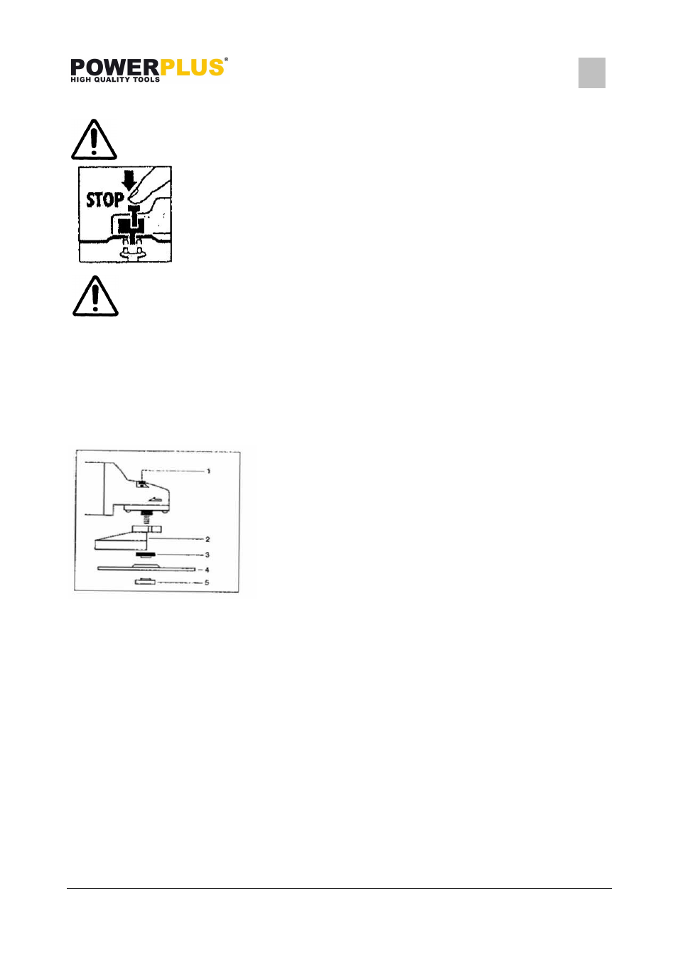
Flange arrangement
1.Spindle catch
2.Guard
3.Clamping flange
4.Grinding wheel
l5. ange nut
7.4
Motor
It is vital for the motor to be well ventilated during operation. Be sure, therefore, to keep the
ventilation holes clean at all times.
7.5
Carbon brushes
Carbon brushes that are burned, broken or shorter than 5 mm are to be replaced by original
replacement brushes. Always replace the carbon brushes in pairs.
7.6
Grinding wheels
Never use a grinding or cutting wheel bigger than specified diameter. Before using a grinding
or cutting wheel, check its rated speed. The wheels rated speed must be higher than the idle
speed of the right-angle grinder.
Use only grinding and cutting wheels that are approved for a maximum speed of 6000 min-1
and a peripheral speed of 80 m/sec.