Introduction & specification, Assembly & installation 4. grinding wheels – Sealey BG150CX User Manual
Page 2
3.1.
unpack the product and check contents against the list below. should there be any damaged
or missing parts contact your supplier immediately.
1. Grinder
2. Eye shield support Plate x 2
3. Eyeshield x 2
4. right & Left Hand tool rests
5. screws & Washers
WARNING! before assembly check to ensure grinder is unplugged from mains.
3.2.
Eyeshield.
3.2.1. Attach eye shield support plates (fig.1.1) to the grinding wheel covers with screws and washers.
3.2.2. fit eye shields (fig.1.2) to support plates with screws, nuts and washers.
3.3.
Tool Rest.
3.3.1. take tool rest (fig 2.1) and align it with bolt holes on the inside of the grinding wheel cover.
3.3.2. secure rest with bolts and washers as shown, ensuring gap between wheel and rest is a
maximum of 2mm.
3.3.3. When both rests have been fitted turn the grinding wheels by hand to confirm clearance.
3.4.
Installation.
3.4.1. the grinder should be mounted on a firm, fireproof surface.
3.4.2. the grinder is supplied with suction feet but may also be bolted or screwed to the work bench
using the base holes provided.
DO NOT get the grinder wet or use in damp or wet locations or areas where there is condensation.
DO NOT use grinder where there are flammable liquids, solids or gases, such as paint solvents and including waste wiping or cleaning rags etc.
DO NOT touch the workpiece close to the ground surface as it will be very hot. Allow to cool. the workpiece may also be very sharp.
DO NOT operate the grinder when you are tired, under the influence of alcohol, drugs or intoxicating medication.
DO NOT leave the grinder operating unattended.
When not in use switch off the grinder, disconnect from the mains power supply and clean the machine and working area.
2. INTRODUCTION & SPECIFICATION
the BG150cX is suitable for workshop use. fitted with wheel guards, adjustable eyeshields and tool rests the grinder is supplied with fine and
coarse grade grinding wheels.
Motor . . . . . . . . . . . . . . . . . . . . . . . . . . .150W/230V
no Load speed . . . . . . . . . . . . . . . . . . . . . 2950rpm
Grinding Wheel size. . . . . . . . . 150 x 16 x 12.7mm
Weight . . . . . . . . . . . . . . . . . . . . . . . . . . . . . . . . 6kg
3. ASSEMBLY & INSTALLATION
4. GRINDING WHEELS
4.1.
MANDATORY SAFETY INSTRUCTIONS. (The following instructions must be observed together with those in Section 1).
DAngEr! use of a damaged wheel (stone) is dangerous and may cause damage and/or personal injury.
WArnIng! Ensure grinder is unplugged from mains supply before attempting to change grinding wheel (stone). only
persons qualified under the “Abrasive Wheels regulations” and holding a current grinding wheel certificate are authorised
to change and dress grinding wheels (stones).
Grinding wheels used with this machine must be of an adequate speed rating and suitable for the material to be ground.
Ensure the maximum speed specification of the wheel is higher than that indicated on the machine data plate.
Check that grinding wheels are secure and that wheels are not worn or damaged, that there are no fissures or cracks. If damaged
replace immediately.
Ensure replacement wheel is not damaged in any way such as cracks, deformations or splinters etc. Also check the mounting flanges
for deformation, burrs or chips. Damaged flanges must
noT be used as they may produce high stresses in the wheel causing it to
break.
Do noT over tighten a wheel. Never tamper with a wheel in order to adapt it to a different size shaft.
Install a new wheel as in 4.2. Once mounted on the grinder test the wheel before use by facing the grinder in a safe direction (point it
away from yourself, others and vulnerable items) and run for a short time. Dress the wheel if necessary.
4.2.
Wheel Changing Procedure. WARNING! Unplug grinder from the mains power supply before changing wheel.
4.2.1. remove the eye shield support plate, loosen and pull the tool rest out as far as possible.
4.2.2. remove the three screws and the corresponding nuts washers and lock washers from the side of the wheel cover and remove.
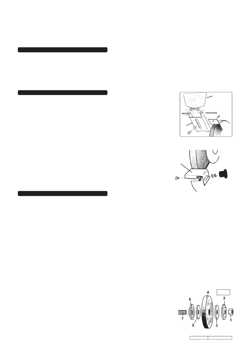
4.2.3. Hold grinding wheel firmly - protect your hands with a cloth, or wear gloves. unscrew retaining nut (fig.3.1).
Note: The nut on the right side of the grinder has standard right-hand thread (undo anti-clockwise). The left side nut has a left-hand
thread and must be loosened by turning clockwise. It may be necessary to strike the wrench sharply in the loosening direction,
with a soft-faced hammer, to loosen the nut.
4.2.4. remove grinding wheel washer (fig.3.2), blotter (3), wheel (4), 2nd blotter (5) and washer (6) from main spindle (7).
4.2.5. carefully inspect the new wheel before installing to ensure there are no fissures, chips, or cracks.
WArnIng! DO NOT USE A DAMAGED WHEEL.
4.2.6. Inspect the blotters - if they are damaged, replace them. the grinder must never be used
without wheel blotters. If none is available when needed, cut the same shape from a piece
of suitable cardboard, for temporary use only.
4.2.7. Install the new wheel by reversing steps above.
Ensure washers (2 & 6) are installed
correctly with the concave side against the blotter.
4.2.8. Hold wheel steady and secure locking nut.
DO NOT over-tighten as this may crack the wheel.
4.2.9. replace wheel cover, replace eye shield, re-adjust tool rest to not more than 2mm from wheel and
tighten securely.
fig. 3
fig. 2
1
2
1
fig. 1
Original Language Version
BG150cX.V3 Issue: 2 - 23/10/09