Introduction & specification, Installation & assembly, Fig.2 fig.3 fig.4 fig.1 – Sealey TP955 User Manual
Page 2
2. INTRODUCTION & SpECIFICATION
The TP955 is a self priming rotary vane type pump with a bypass valve. A 230V direct drive motor is fitted with an overload protector. Flow
control is via a volumetric nutating disc type re-setable meter with large 3 digit display. The unit is supplied with the TP109 delivery nozzle and
4 metres of reinforced 3/4” hose. The system is suitable for wall, tank or pedestal installation.
Voltage . . . . . . . . . . . . . . . . . . . .230V 50Hz
nominal Power . . . . . . . . . . . . . . . 350Watts
Current . . . . . . . . . . . . . . . . . . . . . . . . 3Amp
Speed . . . . . . . . . . . . . . . . . . . . . . 2800rpm
Maximum delivery . . . . . . . . . . . . 56 ltr/min
optimum lifting height. . . . . . . . . . .2 metres
with 1.5” diameter intake pipe
Protection . . . . . . . . . . . . . . . . . . . . . . . IP55
3. INSTALLATION & ASSEmBLY
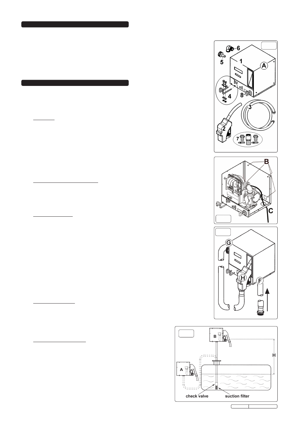
3.1 Unpack the product and check contents against figure 1. Should there be any missing or damaged
parts contact your supplier immediately.
WARNING! This unit must be installed and tested by a qualified fuel system maintenance
engineer. We do not accept any liability for damage or injury caused due to incorrect
installation.
WARNING: DO NOT use conical fittings which can cause damage to seats on pump casing.
ASSEMBLY
3.2 To install the delivery tube support hook ( see kit 4 in fig.1 ) it will be necessary to remove the red
top cover. Undo 3 screws from the right hand side of the cover and the 2 screws from the top
side of the cover and one from above the support hook, lift upwards and tilt towards you.
Loosen the bots on the bottom of the pump and slide the support hook to a desired length then
tighten the bolts making sure that the retaining bar and nuts are holding it in place.
3.3 Uncoil the mains cable and feed it through hole ‘C’ as indicated in fig.2. To make the electrical
connections refer to section 3.11 and the electrical safety advice in Section 1. If the unit is to be
wall mounted this will be done with the cover removed. The fixing holes are indicated by ‘B’ in
fig.2. Replace the top cover.
3.4 Take the reset knob ( item 5 fig.1) and insert it through the hole in the left hand side of the casing
and onto the shaft which is connected to the meter. The shaft has a groove which needs to be
aligned with that on the reset knob.
oUTLET/DELIVERY ConnECTIon
3.5 Remove the plastic transport plug from the outlet hole on the left hand side of the unit (fig.3.G).
Before connecting the delivery pipe ensure all components are free from manufacturing debris or
packaging materials.
3.6 Partially fill pump casing by gently pouring diesel fuel into the outlet hole (fig.3.G) in order to
prime unit ready for use. Screw pipe elbow (fig1.6) into outlet hole (fig.3.G), and connect one
end of delivery hose (fig.1.3) to the elbow, and the other end to delivery nozzle (fig.1.2).
InLET ConnECTIon (Piping Specification.)
3.7 a) The inlet piping must resist a pressure of at least 10 bar and must be not less than 1”
diameter.
b) The tubing/piping must be suitable for low pressure applications.
c) The tubing/piping and accessories used must be suitable for use with diesel fuel.
d) Any curves in the inlet tubing/piping must be of the widest possible radius to aid flow.
3.8 Remove the plastic transport plug from the fuel inlet hole on the underside of the pump
(fig.3.F). Before connecting the inlet suction pipe ensure all components are free from
manufacturing debris or packaging materials. To make the inlet connections the unit is
supplied with a kit (See item 7 fig.1) consisting of two 1“ push-in connectors for use with 1”
flexible tubing with two worm drive hose clips to secure them. The kit also contains a check
valve and filter which must be used at the end of the inlet piping inside the tank, whether
flexible or rigid pipe is used (See fig.4). The check valve and filter must always be immersed at
the bottom of the tank. To aid priming of the pump it is suggested that the inlet pipe be filled
with diesel fuel prior to it being connected to the inlet hole on the underside of the unit (See ‘F’
in fig.3).
3.9 Lower the on/off switch (fig1.8) to ensure the unit is in the oFF mode, and place the nozzle in
its housing (fig3.H).
MoUnTInG THE UnIT
3.10 Whilst the unit can be installed out-of-doors it is recommended that it should be under the
cover of a roof to prolong the units working life and also to provide shelter when dispensing
diesel fuel in bad weather conditions. Careful consideration must be given to the location of the
pump unit to ensure that installation and use of the unit is safe. The unit can be wall,
tank or pedestal mounted. The pump should not be mounted below the fuel
level in a full tank or higher than 2 metres above the maximum fuel level
when a 1” inlet pipe is being used (See fig.4).
ELECTRICAL ConnECTIon
3.11 The connection to the mains supply should be carried out by a qualified
electrician who can advise on the best arrangement for your installation.
The unit can be hard wired directly into a switch unit or connected via a
3-pin plug to the mains supply. In either case weather proof plugs, sockets
and switches should be used. The unit is not equipped with safety switches
and it is therefore recommended that in the absence of any other fuse
arrangements a 30mA circuit breaker is installed upstream of the mains outlet
used. Please refer also to the electrical safety advice given in section 1.
fig.2
fig.3
fig.4
fig.1
Original Language Version
TP955.V2 Issue: 2 - 23/08/10