Priming & operation 5. maintenance, Fig.5 fig.6 – Sealey TP955 User Manual
Page 3
4. pRImING & OpERATION
5. mAINTENANCE
PRIMInG oF THE UnIT
4.1 Care should be taken when priming the pump as the
process could take between several seconds or several
minutes depending on the configuration of the
installation. As previously stated to aid priming of the
pump it is suggested that the inlet pipe be filled with
diesel fuel prior to it being connected to the inlet hole on
the underside of the unit and the pump should be
partially filled by pouring diesel fuel into the pump outlet
before connecting the delivery tube and nozzle.
4.2 Remove the delivery nozzle from its stowage position
and direct it into a suitable container.
4.3 Turn the pump on by lifting up the on/off switch lever (fig.5) then depress the trigger and keep it
depressed until fuel emerges in a steady flow that is free of air.
4.4 If the priming process seems prolonged turn the pump off by lowering the on/off switch lever (fig.6) and
check the following points.
4.5 a) Is the pump running dry?
b) Is the suction pipe airtight and completely immersed in the diesel fuel?
c) Is the suction filter clogged?
d) Has the pump been installed more than 2 metres above the level of the fuel?
e) Has all residual air in all parts of the system been evacuated?
oPERATInG THE UnIT
4.6 To avoid running the pump dry check that the amount of fuel available in the tank is greater than the
amount of fuel to be dispensed. When delivery is complete the end of the suction tube with check valve
and filter should still be completely immersed in the fuel.
4.7 When the unit is turned on, the “by pass” valve on the pump will enable it to operate with the nozzle
trigger closed for approximately 2-3 minutes only. If the dispensing of the fuel is delayed for any reason
the unit should be turned off again.
4.8 Rotate the meter reset knob in an anticlockwise direction to return the display to zero. The cumulative
display below cannot be reset.
4.9 Lift the dispensing nozzle from its rest and check that the trigger lever is in the off position, as shown in
fig.7, before inserting it into the vehicle filler opening or container.
4.10 Turn the pump on by lifting the on/off switch up (See fig.5).
4.11 Press the nozzle trigger and keep it depressed until the desired quantity has been dispensed, then
release the trigger.
4.12 Turn the unit off by lowering the on/off switch (See fig.6) and replace the nozzle onto the rest.
4.13 Hang the delivery tube onto the tube support rest to prevent it being crushed by the wheels of passing
vehicles.
4.14 When a large amount of fuel is to be dispensed it is possible to lock the trigger of the dispensing nozzle
in the ‘on’ position as indicated in fig 8. The operator must remain at the pump at all times to supervise
the entire dispensing process. To unlock the trigger squeeze the lever tightly and the locking bar will
spring out of the way.
The trigger must always be unlocked before the pump is switched off.
WARNING! DO NOT leave the pump operating unattended.
WARNING! DO NOT stow the delivery nozzle back in its housing with the trigger in the locked on
position.
DANGER! Clean up any spillage in accordance with regulations governing the handling of diesel fuels.
fig.7
fig.8
fig.10
fig.9
WEEKLY InSPECTIon
5.1
Clean the entire installation and inspect all piping connections for leaks.
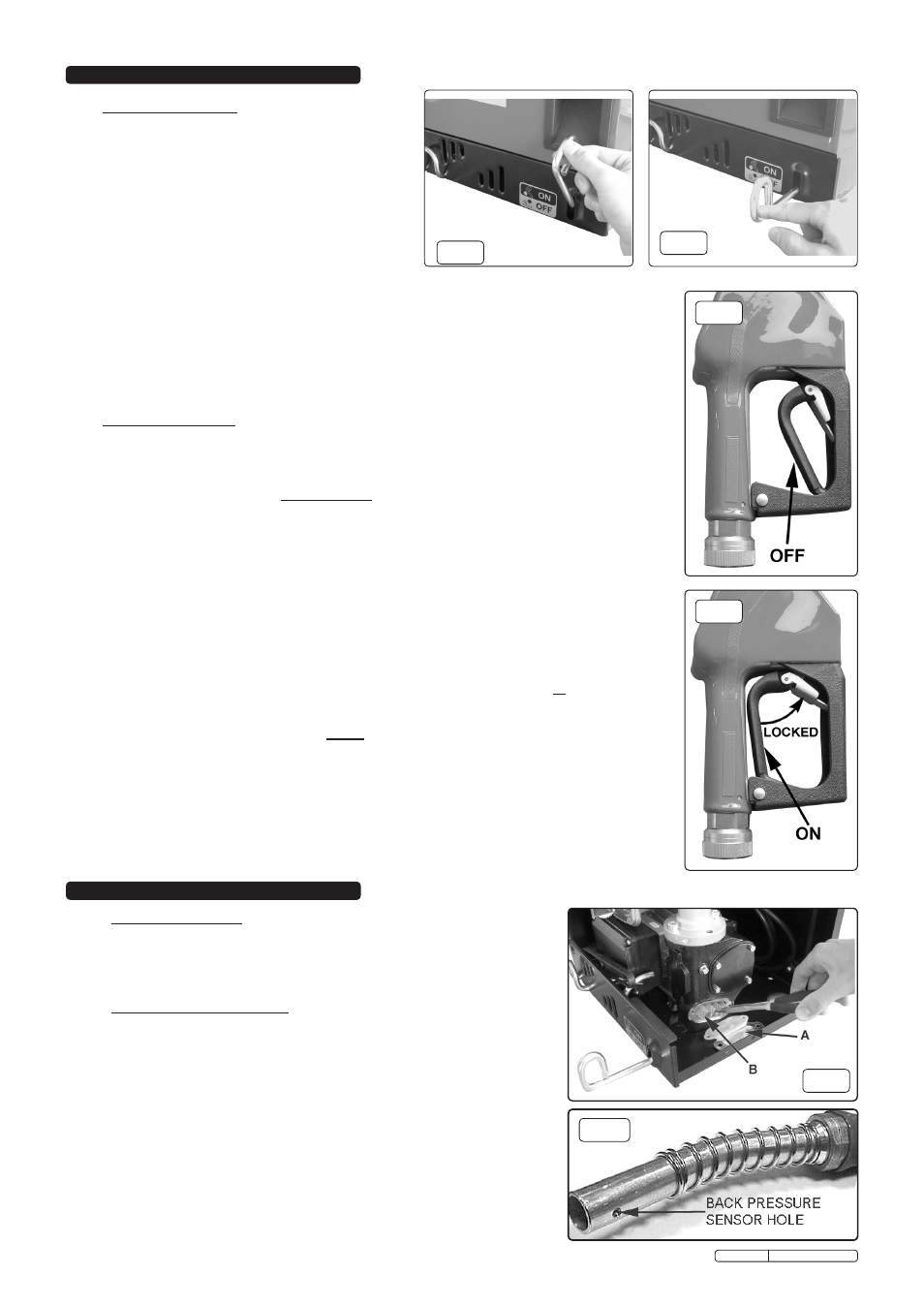
5.2
Inspect the back pressure sensor hole on the dispensing nozzle for blockage
and clean out if necessary (See fig.10).
5.3
Clean the filter and check valve at the end of the suction tube on a weekly basis
and every time the tank is refilled.
CLEAnInG THE PUMP FILTER
5.4
The pump filter should be cleaned on a weekly basis and whenever a reduction
in flow rate is noticed. This may occur in particular when the fuel tank is topped
up which may stir up sediment from in the bottom of the tank.
5.5
To access the pump filter it will be necessary to remove the top cover. Undo 3
screws from the right hand side of the cover and the 2 screws from the top side
of the cover and one from above the support hook, lift upwards and tilt towards
you. Remove the bolts holding the filter cover covering the filter chamber also
remove the rubber seal (fig.9A) and withdraw the filter (fig.9B).
Clean and dry the
filter (blow it through with an airline if available). Put the clean filter back into its
chamber and replace the rubber seal and fliter cover.
5.6
Replace the top cover.
fig.5
fig.6
Original Language Version
TP955.V2 Issue: 2 - 23/08/10