Ab c d – MCZ PowerTherm User Manual
Page 22
Chapter 3
INSTALLATION AND USE MANUAL
page
22
Installation and fitting
Technical service - Rights reserved MCZ S.p.A. - Reproduction prohibited
7) Connect the wiring to the ventilators (and to the light) beofre
completing the cladding, given that all successive operations
can be done from the outside.
If lack of space makes it impossible to use the bracket provided,
proceed in any case so that the kit is firmly fastened, making use of the
built-in box (4).
It is advisable to:
- NOT carry out channelling over 8 m for the forced ventilation.
- In the case that the kit is placed at a certain distance from the
chimney (max 8 m) it is necessary to arrange for adequate
insulation for the piping so that the generated thermal energy is not
dispersed and only heats up the masonry.
If possible, provide ducts of the same distance to prevent different
quantities of air and temperature at different outlets.
3.10.4.
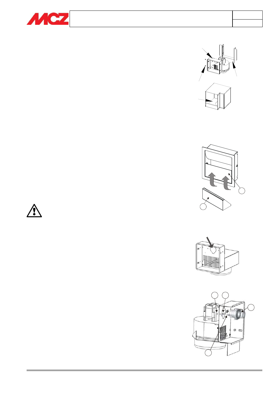
Variation for air outlet with container
The essence container (2) is available only on the one-direction air
outlet with and without light. Its purpose is to humidify the air.
The container (2) can easily be removed from its seat. To do so, lift the
door (1) at the bottom and extract the container (see fig.3).
Place only water in the container.ಞ It is possible to add essences to
perfume the room.
IMPORTANT!
EXTRACT THE CONTAINER FROM ITS SEAT FOR
FILLING ONLY WHEN THE AIR OUTLET IS COOL AND
THE STOVE UNIT IS OFF.
3.10.5.
Variation for air outlet with illumination
If you decide to install the ventilation kit with illumination, you must
remove the knockout panel located on the structure of the air outlet
(fig.4) and pre-install the light (a).
To open the pre-cut knockout panel, strike it with a rubber mallet.
(fig.4).
Install the light (a) on the structure of the air outlet at the knockout
panel so that it is facing the front of the structure (fig. 5). Fasten the
light using the two brackets (c) with the screws (b) and bolts (d)
provided.
Once you have inserted the light (a), make the electrical connections.
In the rear part, insert the two female terminals on the tips of the light
(fig.6)
Connect the power supply for the light (supplied) to a wall switch (not
supplied and responsibility of the installer).
The cable provided for connection of the light is 2.5 metres.ಞ For
greater lengths you will need to use an extension cord.
Figura 2– Installazione kit
Figure 3– Container
1
2
Figure 4– Knockout for insertion of light
a
b
c
d
1
2
3
4
Figure 5– Fastening the light