Fig. 7, Fig. 8, Fig.7 – Medal Sports SMUS1318425 User Manual
Page 11: Fig.8
www.themdsports.com
1318425
10
(Continúe en la siguiente página.)
(Continued on the next page.)
Español
English
FIG. 7
FIG.7
FIG.7
FIG. 8
FIG.8
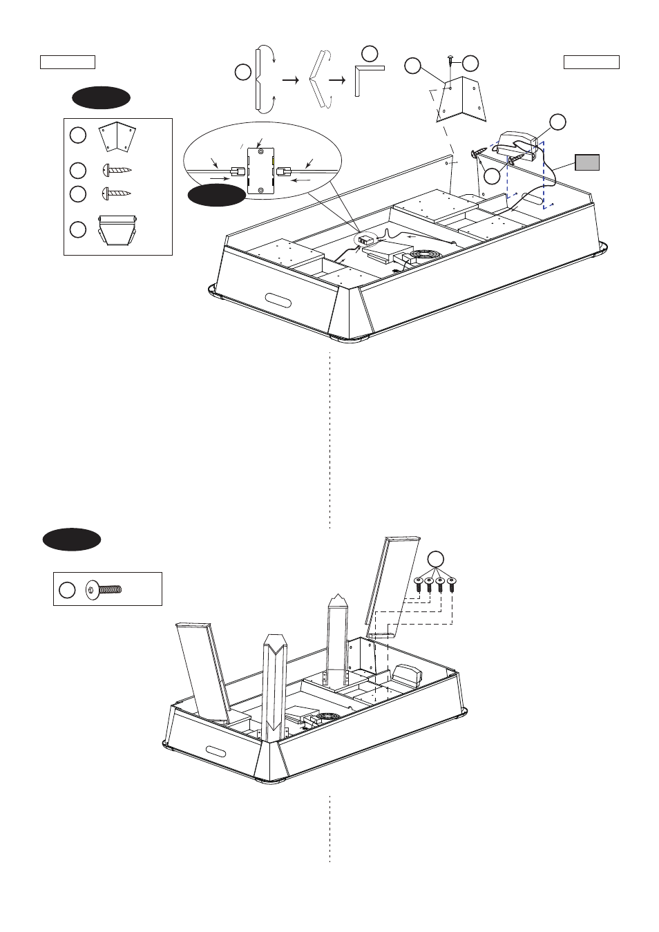
10. Coloque los Delantales de Rincón (#7) entre un
Delantal Lateral (#8) y un Delantal Final (#9)
usando 4 Tornillos (#14) por Delantal de Rincón .
11. Coloque el Colector Puck (#19) al Panel Final (#9)
usando 2 Tornillos (#15) por Panel Final.
12. Inserte los Cables de Sensor desde el Puck
Catcher (#19) a través de las aberturas sobre las
tablas de soporte del Gabinete Principal (#1), y
luego los conecte con la Caja de Conexión(#24).
Vea la FIG. 7 y 7A.
FIG.8
10.
Attach the Apron Corners (#7) between one Side
Apron (#8) and one End Apron (#9 ) using four
Screws (#14) per Apron Corner.
11. Attach the Puck Catcher (#19) to the End Panel (#9)
using two Screws (#15) per End Panel.
12. Insert the Sensor Wires from the Puck Catcher (#19)
through the openings on the support boards of the
Main Cabinet (#1), and then connect them with the
Connect Box (#24). See FIG.7 and 7A.
X 16
X 4
X 4
X 2
7
14
15
19
A1
Caja de Conexión
13.
Place the Legs with Panels (pre-assembled) to
the Main Cabinet using four Bolts (#10) per Leg.
See FIG. 8.
13. Coloque las Piernas con Paneles (pre-
instalado) al Cabinete Principal usando 4
Cerrojos (#10) por Pierna.
Vea la FIG. 8.
X 16
10
10
7
7
7
14
15
19
Connect Box /
Sensor Wire /
Sensor Wire
Cable de Sensor
Cable de Sensor
FIG. 7A