Fig. 10 fig. 11, Fig.10 – Medal Sports SMUS1318425 User Manual
Page 13
www.themdsports.com
1318425
12
(Continúe en la siguiente página.)
(Continued on the next page.)
Español
English
FIG. 10
FIG. 11
22
23
X 2
X 2
FIG.10
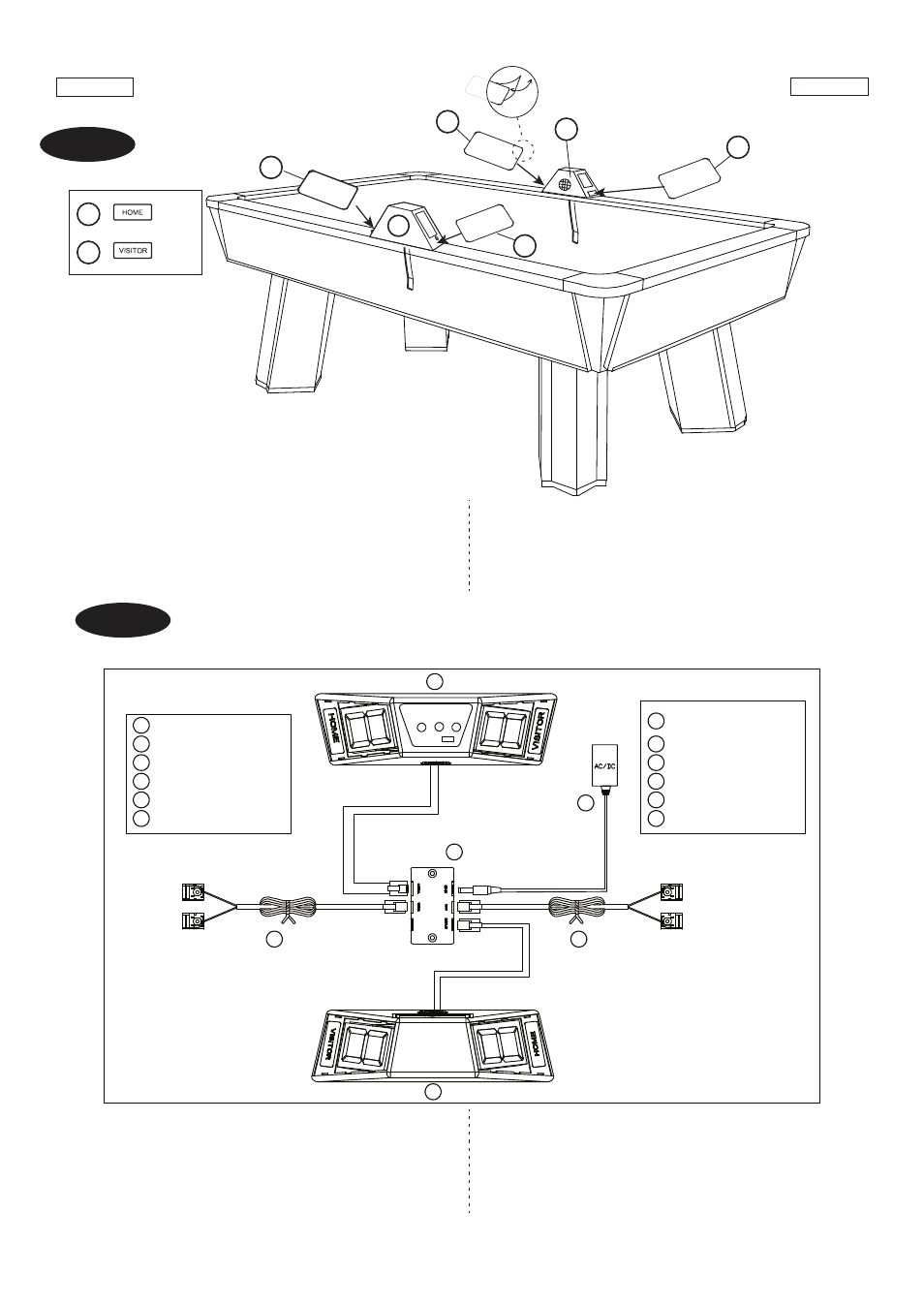
16. Arranque el papel de la parte trasera de las Etiqu-
etas (#22 ) de “HOME” y “VISITOR” y péguelos
a los dos lados de Marcadores (#20 & #21) como
mostrado en la FIG.10.
FIG.10
FIG.11
FIG.11
16. Tear off the backside paper of "HOME" and "Visitor"
Label (#22 & #23) and stick them at two side of
Scorer (#20 & #21) as show in FIG. 10.
24
A1
A1
21
25
20
Scorer with Switch Gear
Scorer
Connect Box
Adapter
24
A1
A1
21
25
20
Puck Catcher Wire
Puck Catcher Wire
x1
x1
x1
x1
x1
x1
Marcador con Engranaje
de Interruptor
Marcador
Caja de Conexión
Adaptador
24
A1
A1
21
25
20
Cable del Colector Puck
Cable del Colector Puck
x1
x1
x1
x1
x1
x1
ELECTRONIC SCORER OPERATION
17. Connect the Scorer Wire (#20 & #21) to the Connect
Box (#24).Plug the Puck Catcher Wire (A1) and
Adapter (#25) to the Connect Box (#24).
17. Conecte el Cable de Marcador (#20 & #21) a la Caja
de Conexión (#24). Enchufe el Cable del Colector
Puck (A1) y el Adaptador (#25) a la Caja de
Conexión(#24).
OPERACION DE MARCADOR ELECTRONICO
23
23
22
21
20
VISIT
OR
HOME
22
HOME
VISIT
OR
HOME