Ill.3 ill.4 montage assembly montage – Multi-Contact MA227 User Manual
Page 2
2/4
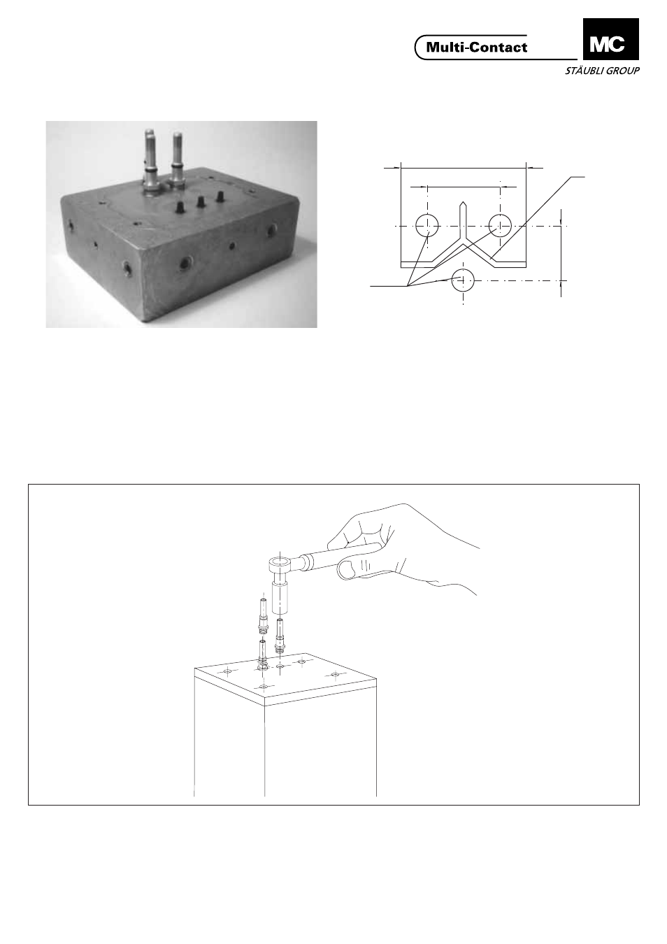
(ill.3)
Kontrollieren Sie:
- dass die Position der Anschluss-
gewinde am Transformator mit den
in der Zeichnung abgebildeten
Massen übereinstimmen.
- dass die Kunststoff-Trennwand (K)
nicht breiter als 60mm ist,
ansonsten muss sie gekürzt werden.
- dass die Beschriftungen nicht mehr
als 1 mm hoch sind, ansonsten
Höhe reduzieren.
(ill.4)
Die 3 Ø 8 mm Stifte von Hand in die
Gewindebohrungen einschrauben und
mit dem Drehmomentschlüssel und
dem SW13 Einsatz anziehen.
Anzugsdrehmoment: 6 Nm.
(ill.3)
Check:
- that the positions of the threaded
connectors on the transformer are in
accordance with the dimensions
shown in the drawing.
- that the plastic dividing wall (K) is
not wider than 60 mm, otherwise it
must be shortened.
- that the labellings are not higher
than 1 mm, otherwise reduce
height.
(Ill.4)
Screw the 3 Ø 8 mm pins by hand
into the threads and tighten with the
torque spanner and the 13 mm insert.
Tightening torque: 6 Nm
(ill.3)
Vérifier que:
- les entraxes de votre transformateur
sont conformes à la disposition type
J (voir croquis ci-dessus).
- la paroi de séparation en plastique
(K) ne dépasse pas une largeur de
60mm.
- les inscriptions ne dépasse pas
1mm de hauteur.
Si nécessaire, couper l'excès de
matière.
(ill.4)
Visser à la main les 3 broches Ø 8mm
dans les taraudages M8 en attente
sur le transformateur. Effectuer le
serrage final avec la clé dynamomé-
trique et la douille de 13 mm au cou-
ple de 6 Nm.
ill.3
ill.4
Montage
Assembly
Montage
60 max.
3xM8
K
28 mm
22 mm
www.multi-contact.com
Advanced Contact Technology