Switching using rose control switching matrix – Rose Electronics UltraMatrix AV DVI 8 User Manual
Page 13
ULTRAMATRIX AV DVI INSTALLATION AND OPERATIONS MANUAL
9
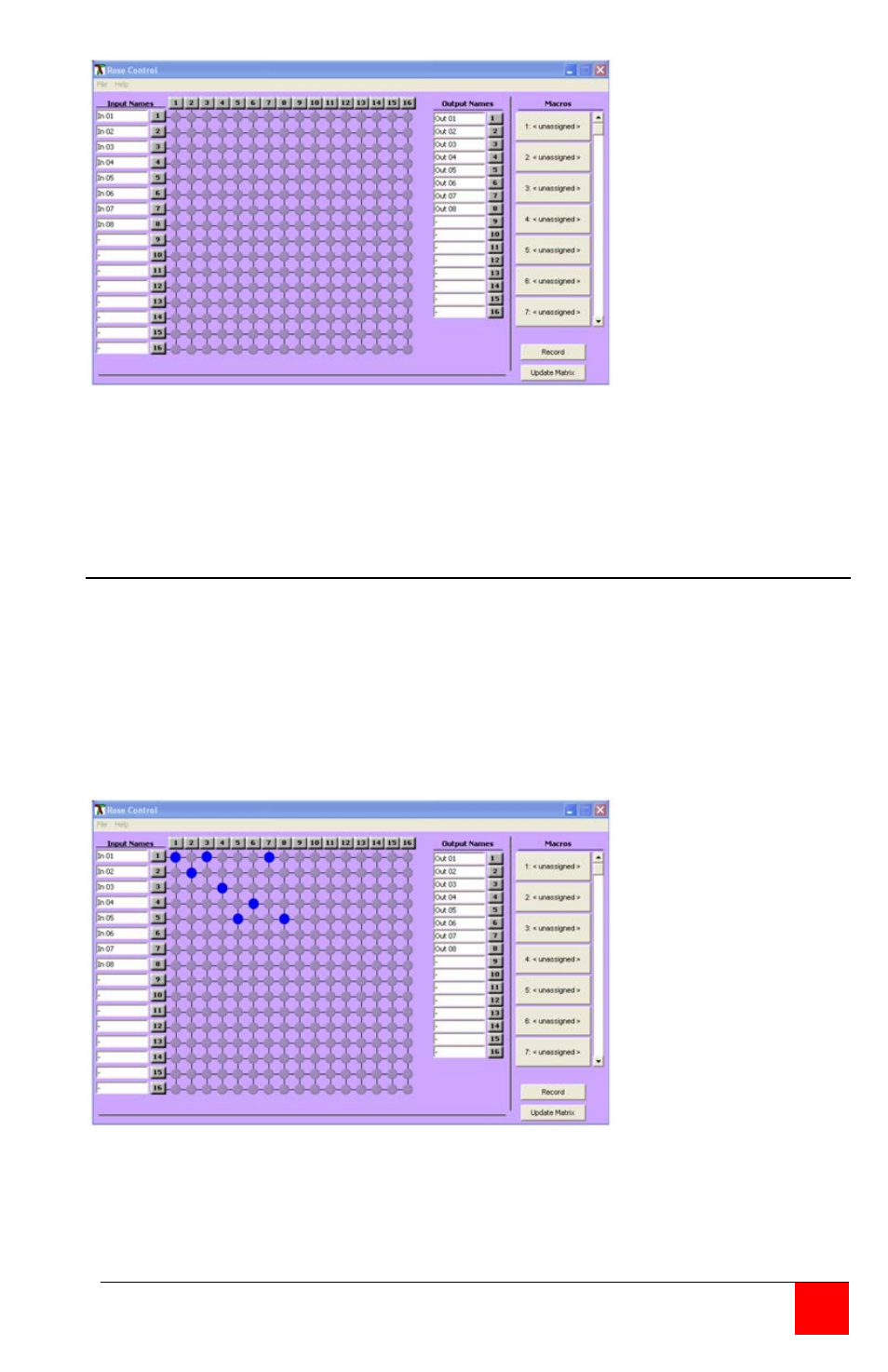
Figure 6. Rose Control Switching Matrix
The left column lists the inputs 1-8 and the right column lists the outputs 1-8.
The input and output names can be changed by highlighting the name to
change and re-naming it.
Switching using Rose Control Switching Matrix
Using the switching matrix is the easiest way to route a video input to any or
all outputs. Click on the cross-point where the input to route (vertical
numbers 1-8) and the output destination (horizontal numbers 1-8) cross and
the switch is executed immediately. The example shown in figure 7 shows
input #1 routed to output #1, #3, and #7, input #2 routed to output #2, input
#3 routed to output #4, Input #4 routed to output #6, Input #5 routed to
output #5 and output #8. Inputs #6, 7, and 8 not assigned. An input can be
routed to multiple outputs, but an output can only be connected to one input.
Figure 7. Example of Switching Matrix
To select multiple outputs to connect to a single input, hold the control (Ctrl)
key down and click on the individual output numbers needed. Next, click on
the input number to route to the selected outputs.