Notice – Thermo Pride Premiere XT 16 SEER User Manual
Page 8
8
4. Replace the corner cover and service access panel removed in
Steps 2 and 4 of the “Field Connections Power Wiring” section.
5. Route the 24-volt control wiring (NEC Class 2) from the outdoor unit
to the indoor unit and thermostat.
6. All field wiring to be in accordance with national electrical codes
(NEC) and/or local-city codes.
7. Mount the thermostat about 5 ft. above the floor, where it will be
exposed to normal room air circulation. Do not place it on an outside
wall or where it is exposed to the radiant effect from exposed glass
or appliances, drafts from outside doors or supply air grilles.
DEHUMIDIFICATION CONTROL
A dehumidification control accessory 2HU06700124 may be used with
variable speed air handlers or furnaces in high humidity areas. This
control works with the variable speed indoor unit to provide cooling at a
reduced air flow, lowering evaporator temperature and increasing latent
capacity. The humidistat in this control opens the humidistat contacts on
humidity rise. To install, refer to instructions packaged with the acces-
sory and Figures 8 - 13. Prior to the installation of the dehumidification
control, the jumper across the HUMIDISTAT terminals on the indoor
variable speed air handler or furnace CFM selection board must be
removed.
During cooling, if the relative humidity in the space is higher than the
desired set point of the dehumidification control, the variable speed
blower motor will operate at lower speed until the dehumidification con-
trol is satisfied. A 40-60% relative humidity level is recommended to
achieve optimum comfort.
If a dehumidification control is installed, it is recommended that a mini-
mum air flow of 325 cfm/ton be supplied at all times.
INDOOR CFM CONFIGURATION
For proper system operation the indoor CFM must be set properly.
Refer to the Technical Guide for the outdoor unit for the recommended
air flow settings for each size condensing unit and matching indoor unit.
Set the cooling speed per the instructions for the air handler or furnace.
Verify the airflow.
If installed as a communicating system (outdoor, indoor, and thermo-
stat), the system will automatically adjust to the optimal airflow settings.
These parameters can also be modified using the Touch Screen Com-
munication Control. Refer to the Touch Screen Communication Control
owner’s manual for this procedure. Manual setting of the airflow jump-
ers on the ID equipment is not necessary with the Touch Screen Com-
munication Control.
Ambient temperature sensor should extend below corner cover by 1”.
To eliminate erratic operation, seal the hole in the wall at the thermo-
stat with permagum or equivalent to prevent air drafts from affecting
the operation of the thermostat.
NOTICE
NOTICE
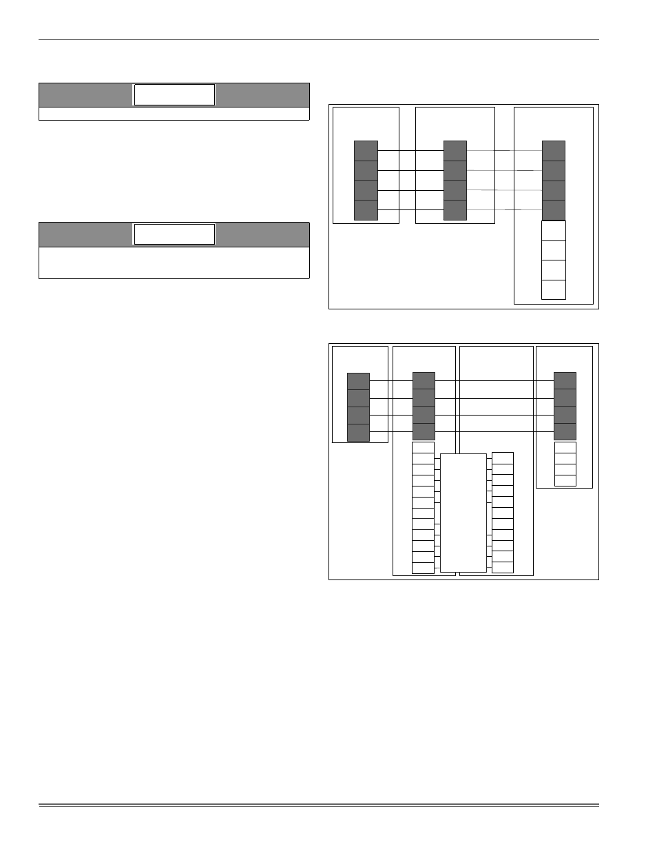
FIGURE 8: Communicating HP with Communicating Air Handler or
Furnace
FIGURE 9: Communicating HP with Non-Communicating Air Handler
or Furnace using Communicating Interface Control
R
C
Y1
Y2
Touch Screen
Communicating
Control
Air Handler/Furnace
Communicating
Control
Heat Pump
Communicating
Control
GND
or C
GND
or C
B-
R
A+
GND
or C
GND
or C
B-
R
A+
GND
or C
GND
or C
B-
R
A+
R
C
Y1
Y2
HUM
W2
DHUM
W
G
C
R
O
Y
Y2
HUM
W2
DHUM
W
G
C
R
O
Y
Y2
Touch Screen
Communicating
Control
Communicating
Indoor
Interface Control
Non-Communicating
Indoor Unit
Heat Pump
Communicating
Control
Wire per
non-comm.
installation
manual
Assume that
connections
are from
thermostat
GND
or C
GND
or C
B-
R
A+
GND
or C
GND
or C
B-
R
A+
GND
or C
GND
or C
B-
R
A+