Programming control port i/o pin assignments -3, Able 2-3 for, Able 2-4 for pin assignmen – KEPCO KLN Series (750W, 1500W, 3000W), Main Contro Firmware Version 1.70 and higher User Manual
Page 29
KLN Series 051614
2-3
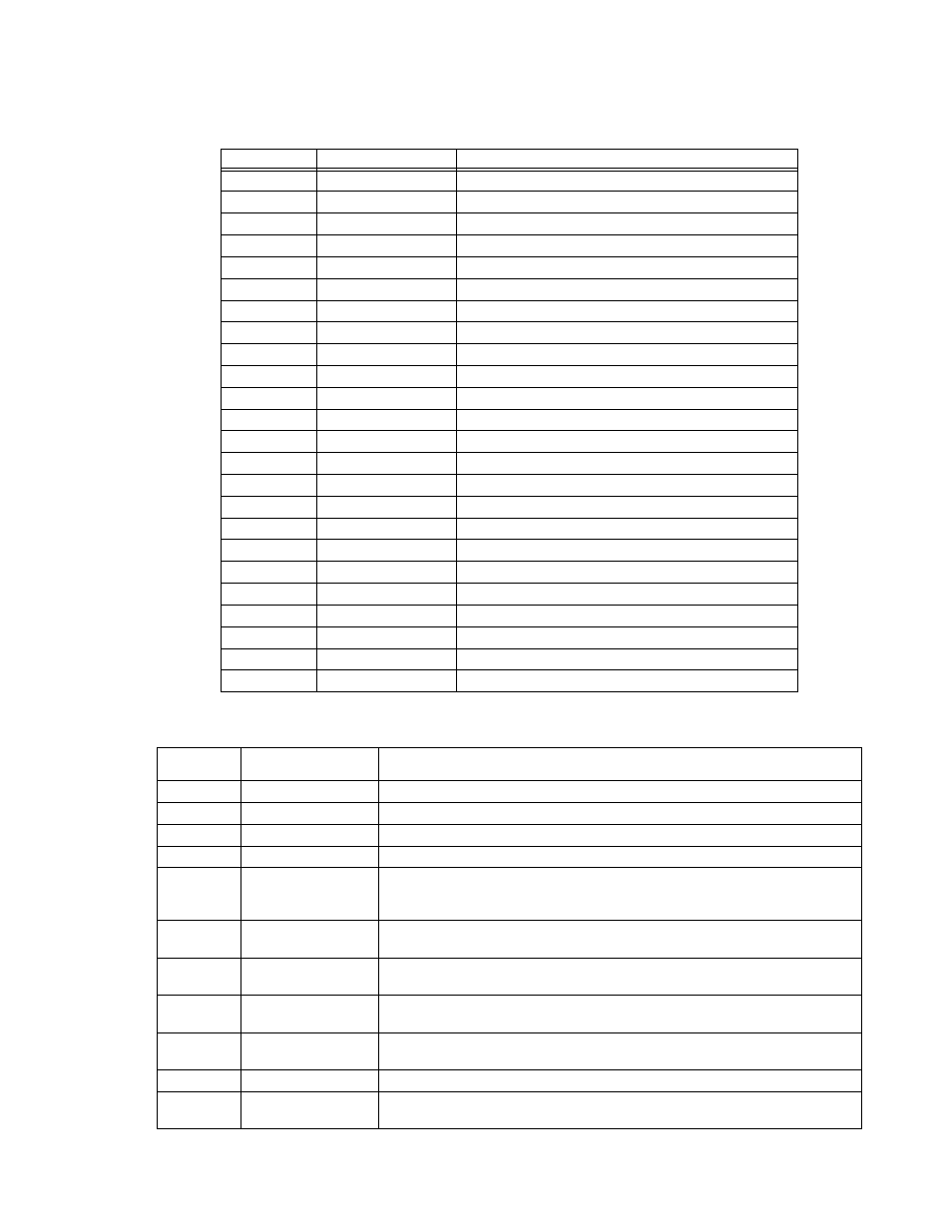
TABLE 2-3. GPIB (IEEE 488) PORT INPUT/OUTPUT PIN ASSIGNMENTS
PIN
SIGNAL NAME
FUNCTION
1
D
I
01
I/O Line
2
D
I
02
I/O Line
3
D
I
03
I/O Line
4
D
I
04
I/O Line
5
EOI
End or Identify
6
DAV
Data Valid
7
NRFD
Not Ready for Data
8
NDAC
Not Data Accepted
9
IFC
Interface Clear
10
SRQ
Service Request
11
ATN
Attention
12
SHIELD
Shield
13
D
I
05
I/O Line
14
D
I
06
I/O Line
15
D
I
07
I/O Line
16
D
I
08
I/O Line
17
REN
Remote Enable
18
GND
Ground (signal common)
19
GND
Ground (signal common)
20
GND
Ground (signal common)
21
GND
Ground (signal common)
22
GND
Ground (signal common)
23
GND
Ground (signal common)
24
LOGIC GND
Logic Ground
TABLE 2-4. PROGRAMMING CONTROL PORT I/O PIN ASSIGNMENTS
PIN
SIGNAL NAME
FUNCTION
1, 2
RECALL
External recall control (dry contact). Same function as RCL key on front panel.
3, 4, 5, 6
---
Not used
7
Power on/off status
Output signal. Active (low between pin 7 and pin 8) to indicate unit is turned on.
(1)
8
Status common
Common for Status signal pins 7, 9, 10, 11 and 12
(1)
9
Alarm status
Output signal. Active (low between pin 9 and pin 8) to indicate whether alarm (OVP or
OCP trips or shutdown signal applied to pin 23) has occurred. (open collector via opto-
coupler).
(1)
10
On/off status
Output signal. Active (low between pin 10 and pin 8) to indicate output is on (open col-
lector by optocoupler).
(1)
(See PAR. 3.3.38 to enable.)
11
CC status
Output signal. Active (low between pin 11 and pin 8) to indicate unit is in constant cur-
rent mode (open collector by optocoupler).
(1)
12
CV status
Output signal. Active (low between pin 12 and pin 8) to indicate unit is in constant volt-
age mode (open collector by optocoupler).
(1)
13
EXT 5V input+
Auxiliary output voltage. Used to supply +5V for the relay providing remote output
on/off function.
14
EXT V input common
Common for Pin 13 (remote output on/off function).
15
PRL IN+
Input signal. For units operating in parallel, used for signal input into MASTER of cur-
rent sharing between MASTER and SLAVE(s) (see PAR. 2.8.2).