Appropriate usage, Feature diagram – Amprobe AC50A User Manual
Page 6
��
Appropriate Usage
• The instrument may only be used under those conditions and for those
purposes for which it was conceived. For this reason, in particular the
safety references, the technical data including environmental condi-
tions and the usage in dry environments must be followed.
• When modifying or changing the instrument, the operational safety
is no longer ensured.
• The instrument may only be opened by an authorised service technician,
e.g. for fuse replacement.
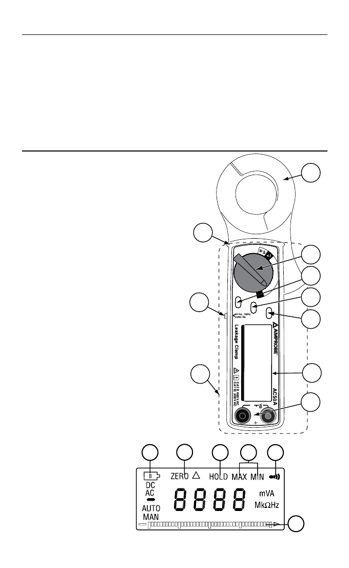
Feature Diagram
1. Induction coil (clamp)
2. Selector switch, for type of
measurement
3. Data hold button, to memorise
reading
4. MIN/MAX value (page 8)
5. Zero setting / relative value func-
tion. Once this button is pressed,
the current reading shall be set
to zero and be used as a zero re-
ference value for all other subse-
quent measurement.
6. Frequenzy range select switch. At
50/60Hz position, only the low fre-
quency signal is measured. At Wide
position, signal from 40 - 1kHz is
measured.
7. Digital display
8. Input socket, for measuring vol-
tage, resistance, continuity tes-
ting
9. Hand-hold area incl. Barrier (9a)
10. Low-battery symbol
11. Zero Point / Relative Value Symbol
12. Hold symbol (Data Hold is active)
13. Min/ Max Symbol
14. Continuity Symbol
15. Analogue Bargraph
4
40
mA
4
A
60
A
40
A
OFF
Z
ER
O
M
IN
/M
AX
HO
L
D
COM
0
10
20
30
40
600
V
A
C
40
0
mA
1
6
2
3
4
5
7
8
9
9a
10
11
12
13
14
15