Before operation, Warning, 1 how to connect test leads – Amprobe AMB-25 Insulation-Tester User Manual
Page 4: 2 battery check & replacement, 3 auto-power-off, 4 test leads check
6
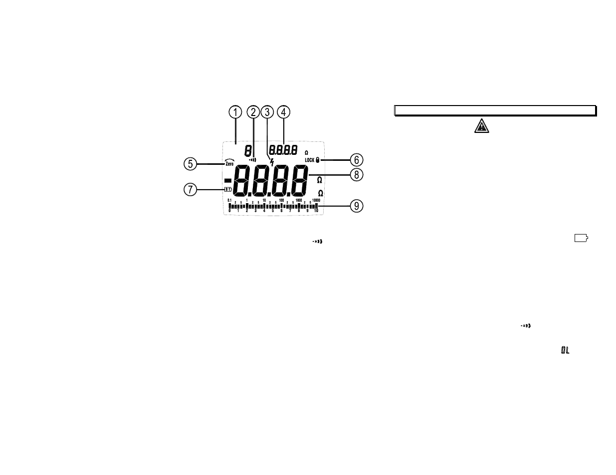
Display :
DC
MEM
READ
M
V M
4. BEFORE OPERATION
Warning
To avoid electrical shock remove test leads before opening case or
battery cover. Do not operate with battery cover open.
To avoid electrical shock when performing resistance tests, remove
all power from the circuit to be measured.
To avoid electrical shock, first connect the test leads to the meter
inputs before you make connection to the circuit under test.
To avoid electrical shock, do not touch test lead tips, test points or
terminals when pressing TEST.
4-1 How to connect test leads.
Connect the red test lead into the “ VΩ ” terminal and the black
lead into the “ COM ” terminal.
4-2 Battery Check & Replacement
c
Manual data memory and read location indicator.
1). If battery power is not sufficient, LCD will display “
BT
”.
Replacement of 6 pcs new batteries, type 1.5V size “AA” is required.
d
Beeper symbol shows if beeper turned on in Ω
function.
e
High voltage warning symbol flashes, if voltage ≧ 30V is present on the
probes.
2). Use a screw drive to unscrew the screw secured on battery cover.
Take out the used batteries and replace 6 pcs new batteries.
3). Place back the battery cover and secure the screw.
f
Resistance reading held from the last measurement in MΩ and Ω
function.
4-3 Auto-Power-Off
g
Zero symbol is on if test leads are zeroed out.
1). The meter automatically turns off after 15 minutes of non-use.
2). To turn the meter back on, turn the rotary switch to OFF, then to
the desired function.
h
Lock symbol is on if the TEST mode is locked in MΩ functions.
i
Low battery symbol.
4-4 Test Leads Check
j
Main display reading for all functions.
Set the range select switch to the “Ω
” range. Connect the
crocodile clips with the test lead tips, Clip alligator clips with lead
other. The indicator should read <0.5Ω. When the leads are not
connected the display will read infinity indicated by “-
-
”. This
will ensure that test leads are under working condition.
k
Analog bar graph displays resistance on a logarithmic scale and
voltage on a linear scale. The value always tracks the main display.