Lsisas3442x and lsisas3442xl board layout, Figure 3.2 – Avago Technologies LSI SAS 3041X-R User Manual
Page 29
Characteristics of the PCI-X to 3.0 Gbit/s SAS Host Adapters
3-5
Version 2.1
Copyright © 2005, 2006 by LSI Logic Corporation. All rights reserved.
target typically converts the output signals into multiple parallel LED
signals and provides the input signals from general-purpose inputs. The
SGPIO signals are SCLOCK on pin 14, SLOAD on pin 15, SDATAOUT
on pin 18, and SDATAIN on pin 19.
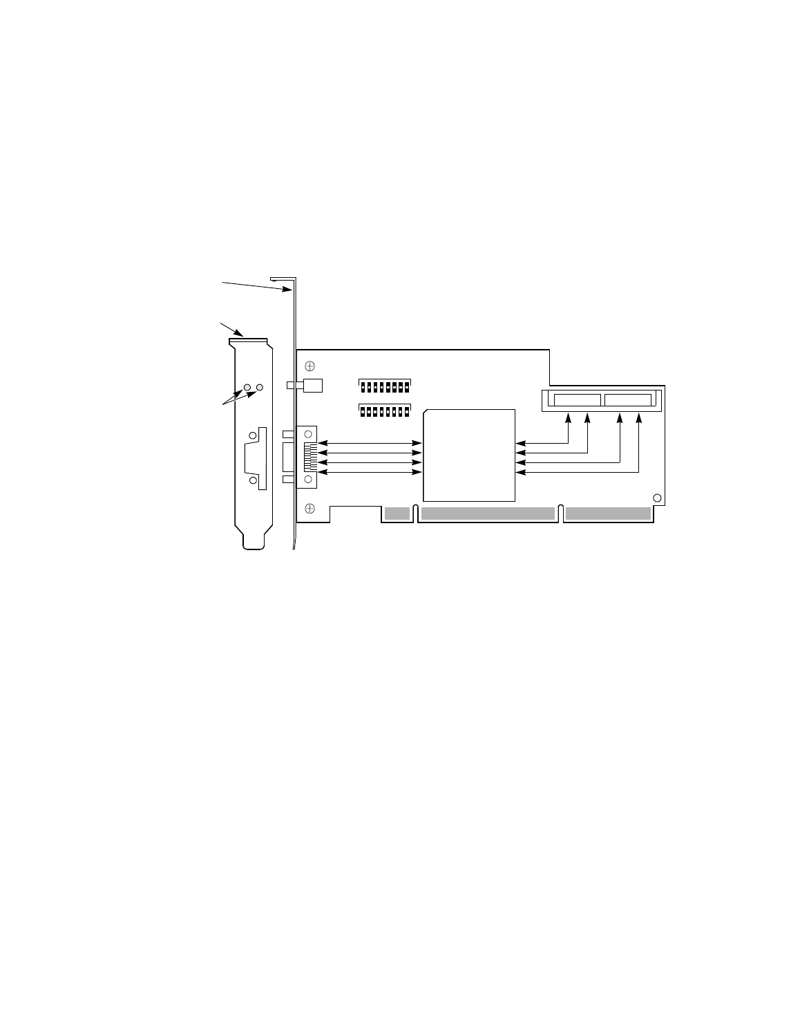
Figure 3.2
LSISAS3442X and LSISAS3442XL Board Layout
•
J1: PCI/PCI-X 64-bit, +3.3 V type board edge connector
•
J2: SFF-8470 SAS external right-angle connector
•
J5: SFF-8484 SAS internal right-angle connector with four sideband
lines
3.1.2.3
Physical Characteristics
The LSISAS3442X and LSISAS3442XL boards are 6.6 inches x 2.536
inches. PCI/PCI-X connection is made through the edge connector J1.
The component height on the top and bottom of the LSISAS3442X and
LSISAS3442XL boards follows the PCI/PCI-X specifications.
J1
J5
J2
LSISAS1068
Standard PCI Bracket
(LPPCI)
Low-Profile
Link Not
Activity
PCI Bracket
LEDs
LEDs
LSISAS3442X
LSISAS3442XL
Two Light Pipes,
One Green and
One Bi-color
Present