Sony SELP28135G 28-135mm f/4.0 G Power Zoom FE User Manual
Sony Lenses
–1
–2
(1)
(2)
E
A
http://www.sony.co.jp/DSLR/support/
•
•
•
•
•
AF
AF
OFF
•
•
•
2
1
2 PUSH
3
4
5
6
7
* 8
9
10
11
12 IRIS LOCK
13
14
15
16 POWER ZOOM
17 ZOOM
18
19
20
21
22
23
*
–
1
2
•
•
–
1
•
2
•
•
1
•
2
3
(1)
(2)
(1)
(2)
(3)
(4)
4-542-899-
02(1)
©2014 Sony Corporation
SELP28135G
Interchangeable Lens
Objectif interchangeable
Operating Instructions
Mode d’emploi
Manual de
instrucciones
E-mount
Printed in Japan
FE PZ 28-135mm F4 G OSS
3.3
5
7
10
15
30
4
0.95
1.5
2
3
5
10
1.2
AF/MF
FULL MF
OPTICAL
STEADY SHOT
ON OFF
3
4
•
•
•
PUSH(
)
1
2
•
POWER ZOOM
1
ZOOM
SERVO
2
POWER ZOOM
POWER ZOOM
T
Telephoto
W
Wide
1
ZOOM
MANUAL
2
ˎ
ˎ
ZOOM
SERVO
MANUAL
W/T
AF/MF
FULL MF
•
•
AF/MF
FULL MF
AF/MF
0.4 m (W) – 0.95 m (T)
FULL MF
0.95 m
•
AF/MF
FULL MF
IRIS LOCK
LOCK
A
F4
F22
RELEASE
A
F22
A
F4
F22
M
A
F
OFF
-a
ON
•
ON
•
OFF
FE PZ 28-135mm F4
G OSS
SELP28135G
mm
28-135
35mm
*
1
mm
42-202.5
To change vertical/horizontal
position
Loosen the collar-locking knob on the tripod-mounting
collar (1) and rotate the camera either direction. The
camera can be quickly switched between vertical and
horizontal positions while maintaining stability when
using a tripod.
ˎ
ˎ
There is a White dot (collar index) on the collar.
Align a
white dot on the tripod-mounting collar with the white
line (collar index) on the lens to adjust the camera
position precisely (2).
ˎ
ˎ
Tighten the collar-locking knob firmly after the camera
position is set.
ˎ
ˎ
The collar may hit the camera body or accessory when
rotated, depending on the camera or accessory model.
For more information on compatibility with cameras
and accessories, visit the web site of Sony for your area.
To detach the tripod-mounting collar
from the lens
The tripod-mounting collar can be detached from the
lens when not using a tripod.
1
Remove the lens from the camera.
ˎ
ˎ
See “
Attaching/detaching the lens” for details.
2
Turn the collar-locking knob, to align
the marks of collar-locking knob and
the collar (3).
3
Pull the collar-locking knob down (4),
and open the collar.
ˎ
ˎ
Hold the lens and the collar firmly when opening
the collar.
ˎ
ˎ
Do not hold the hinge when opening the collar. If
you hold the hinge you may pinch your hand.
ˎ
ˎ
If you open the collar without removing the lens
from the camera, the collar may hit the camera
body or accessory. We recommend you remove the
lens from the camera before detaching the collar.
Attaching the lens hood
It is recommended that you use a lens hood to
reduce flare and ensure maximum image quality.
Align the mark on the lens hood with the
lens hood index on the lens, then insert the
lens hood into the lens mount and rotate it
clockwise until it clicks into place.
To remove the lens hood
Hold the PUSH (lens hood release) button down and
turn the lens hood in the opposite direction of when
attaching.
Attaching the strap
Attach the strap to the lens when carrying the lens
with the interchangeable lens camera (still) attached.
Follow steps (1) and (2) to attach the strap.
ˎ
ˎ
To prevent the lens from dropping, be sure to attach
the strap properly so that the strap will not come loose
from the lens.
Zooming
Using the POWER ZOOM lever
1
Set the ZOOM switch to SERVO.
2
Move the POWER ZOOM lever to adjust
the focal distance (zoom position).
Move the POWER ZOOM lever toward T
(Telephoto) to zoom in.
Move the POWER ZOOM lever toward W (Wide) to
zoom out.
Using the zoom ring
1
Set the ZOOM switch to MANUAL.
2
Rotate the zoom ring to adjust the focal
distance (zoom position).
ˎ
ˎ
When you slide the ZOOM switch from SERVO to
MANUAL, the focal length may automatically change.
To change the rotating direction of the
zoom ring operation
Some cameras can be assigned to either W or T,
by rotating the zoom ring. For details, refer to the
Instruction Manual of the camera.
Focusing
To adjust the focus in AF/MF mode
When using the autofocus function together with
manual focus or when recording movies, set the
focusing ring to position
.
To adjust the focus in FULL MF mode
If you do not want to use autofocus, set the focusing
ring to position
and adjust the focus manually.
ˎ
ˎ
The distance scale is only a rough guide.
ˎ
ˎ
The minimum focuses are different in AF/MF mode and
in FULL MF mode.
In AF/MF mode: 0.4 m (W) – 0.95 m (T)
In FULL MF mode: 0.95 m in all area
ˎ
ˎ
When you move the focus ring from AF/MF mode
to FULL MF mode
, focus is adjusted to the distance
indicated on the distance scale.
Adjusting the exposure
IRIS LOCK switch
LOCK:
You can lock the iris ring at “A” on the
aperture scale, or rotate it between f/4 and
f/22.
RELEASE: You can rotate the iris ring between “A” and
f/22 on the aperture scale.
When you align “A” on the aperture scale to the
aperture index, the camera is set to auto iris mode
and the exposure is set by the camera. And you can
adjust the amount of light manually between f/4 and
f/22 by rotating the iris ring.
FE PZ 28-135mm F4
G OSS
SELP28135G
12-18
1*
2
75°-18°
2*
2
54°-12°
*
3
m
0.4-0.95
0.15
F22
mm
95
mm
105 × 162.5
g
1,215
*
1
35mm
APS-C
*
2
1 35mm
2 APS-C
*
3
•
1
1
1
1
1
1
1
This instruction manual explains how to use
lenses. Notes on use are found in the separate
“Precautions before using”. Be sure to read both
documents before using your lens.
This lens is designed for Sony α camera system
E-mount cameras. You cannot use it on A-mount
cameras.
For further information on compatibility, visit the web
site of Sony in your area, or consult the dealer of Sony
or local authorized service facility of Sony.
Notes on use
ˎ
ˎ
When carrying a camera with the lens attached, always
firmly hold both the camera and the lens.
ˎ
ˎ
This lens is not water-proof, although designed with
dust-proofness and splash-proofness in mind. If using
in the rain etc., keep water drops away from the lens.
ˎ
ˎ
The zoom pin can be attached to and detached from
the zoom ring.
ˎ
ˎ
Be careful not to drop the lens when storing and
carrying it. Use a sturdy tripod for shooting.
ˎ
ˎ
AF illuminator of the camera may be blocked by the
lens. We recommend that you set the AF illuminator
to OFF.
Precautions on using a flash
ˎ
ˎ
You cannot use a built-in camera flash with this lens.
Use an external flash (sold separately).
ˎ
ˎ
When using a flash, the lens may partially block the
light of the flash, resulting in a shadow at the bottom
of the picture.
Vignetting
ˎ
ˎ
When using the lens, the corners of the screen become
darker than the center. To reduce this phenomena
(called vignetting), close the aperture by 1 to 2 stops.
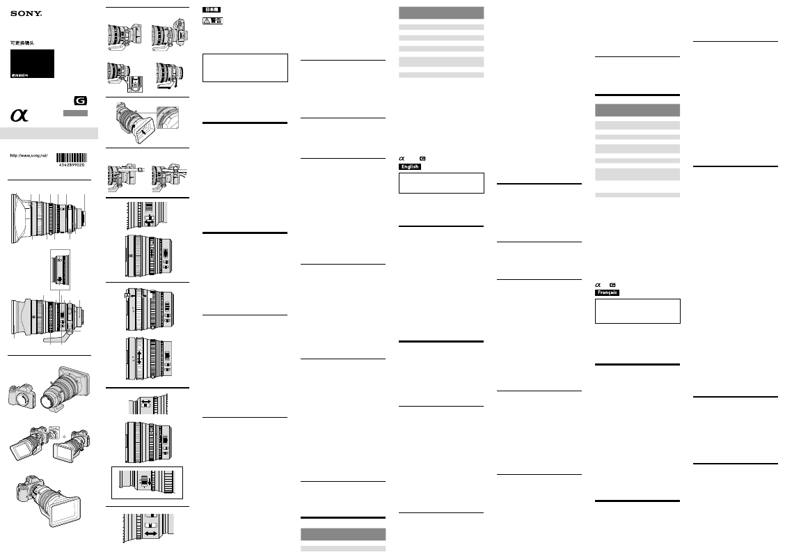
Identifying the parts
1 Lens hood 2 PUSH (lens hood release) button
3 Focusing ring 4 Zoom ring 5 Iris ring
6 Collar index 7 Lens contacts*
8 Tripod-mounting collar 9 Aperture index
10 Distance index 11 Lens hood index
12 IRIS LOCK switch 13 Iris click switch
14 Distance scale 15 Aperture scale
16 POWER ZOOM lever 17 ZOOM switch
18 Strap hooks 19 Lens mounting index
20 Collar-locking knob 21 Shake compensation switch
22 Zoom pin
23 Hood cap
* Do not touch the lens contacts.
Attaching/detaching the lens
To attach the lens
(See illustration
–.)
1
Remove the rear lens cap and the
camera body cap.
2
Align the white dot on the lens barrel
with the white dot on the camera
(mounting index), then insert the lens
into the camera mount and rotate it
clockwise until it locks.
ˎ
ˎ
Do not press the lens release button on the camera
when mounting the lens.
ˎ
ˎ
Do not mount the lens at an angle.
To remove the lens
(See illustration
–.)
While holding down the lens release button on
the camera, rotate the lens counterclockwise until
it stops, then detach the lens.
Using the tripod
When using a tripod, attach it to the-mounting collar
of the lens, not to the tripod receptacle of the camera.
Adjust the amount of light manually
Rotate the iris ring to the desired exposure
(f-stop) when the camera is set to the M mode
or A mode.
Notes
Set the iris click switch to OFF when shooting movies.
(See illustration
-a)
If you change the aperture value while shooting a
movie with the iris click switch set to ON, the sound of
the iris ring will be recorded.
Using the shake compensation
function
Shake compensation switch
ˎ
ˎ
ON: Compensate for camera shake.
ˎ
ˎ
OFF: Does not compensate for camera shake. We
recommend using a tripod during shooting.
Specifications
Name (Model name)
FE PZ 28-135mm F4
G OSS
SELP28135G
Focal length (mm)
28-135
Equivalent 35mm-format focal
length*
1
(mm)
42-202.5
Lens groups-elements
12-18
Angle of view 1*
2
75°-18°
Angle of view 2*
2
54°-12°
Minimum focus*
3
(m (feet))
0.4-0.95
(1.31- 3.12)
Maximum magnification (×)
0.15
Minimum aperture
f/22
Filter diameter (mm)
95
Dimensions
(maximum diameter × height)
(approx., mm (in.))
105 Ч 162.5
(4 Ч 6 1/2)
Mass (approx., g (oz))
(excluding tripod-mounting
collar)
1,215 (42.9)
Shake compensation function
Yes
*
1
The values shown above for equivalent 35mm-format
focal length are for Interchangeable Lens Digital
Cameras equipped with an APS-C sized image sensor.
*
2
Angle of view 1 is the value for 35mm cameras, and
angle of view 2 is the value for Interchangeable Lens
Digital Cameras equipped with an APS-C sized image
sensor.
*
3
Minimum focus is the distance from the image sensor
to the subject.
ˎ
ˎ
Depending on the lens mechanism, the focal length
may change with any change in shooting distance. The
focal lengths given above assume the lens is focused
at infinity.
Included items: Lens (1), Rear lens cap (1), Lens hood
(1), Hood cap (1), Lens case (1), Strap (1), Zoom pin (1),
Set of printed documentation
Designs and specifications are subject to change
without notice.
and
are trademarks of Sony Corporation.
Ce mode d’emploi explique comment se
servir des objectifs. Les remarques concernant
l’emploi se trouvent dans le document distinct
« Précautions avant toute utilisation ». Veuillez lire
les deux documents avant d’utiliser votre objectif.
Votre objectif est conçu pour les appareils photo
pourvus d’une monture E de type Sony α. Il ne peut
pas être utilisé pour les appareils photo pourvus
d’une monture A.
Pour plus d’informations sur la compatibilité,
consultez le site de Sony de votre pays, ou adressez-
vous à un revendeur Sony ou à un service après-
vente agréé Sony.
Remarques sur l’emploi
ˎ
ˎ
Lorsque vous portez un appareil photo sur lequel est
installé l’objectif, tenez toujours fermement l’appareil
photo et l’objectif.
ˎ
ˎ
Cet objectif n’est pas étanche bien qu’il soit conçu pour
résister à la poussière et aux éclaboussures. Si vous
l’utilisez sous la pluie, etc., veillez à ce que de l’eau ne
tombe pas dessus.
ˎ
ˎ
La goupille de zoom peut être posée ou déposée de la
bague de zoom.
ˎ
ˎ
Faites attention de ne pas faire tomber l’objectif lors de
son rangement ou transport. Utilisez un trépied robuste
lors de la prise de photos.
ˎ
ˎ
L’illuminateur AF de l’appareil photo peut être bloqué
par l’objectif. Nous conseillons de régler la position de
l’illuminateur AF sur OFF.
Précautions concernant l’emploi d’un flash
ˎ
ˎ
Vous ne pouvez pas utiliser le flash de votre appareil
photo avec cet objectif. Utilisez un flash externe (vendu
séparément).
ˎ
ˎ
Lors de l’utilisation d’un flash, l’objectif peut bloquer
partiellement la lumière du flash et produire une ombre
au bas de l’image.
Vignetage
ˎ
ˎ
Lorsque l’objectif est utilisé, les coins de l’écran
deviennent plus sombres que le centre. Pour réduire
ce phénomène (appelé vignetage), fermez l’ouverture
d’un ou de deux crans.
Identification des éléments
1 Parasoleil de l’objectif
2 Bouton PUSH (libération du parasoleil)
3 Bague de mise au point 4 Bague de zoom
5 Bague d’iris 6 Repère de cadre
7 Contacts d’objectif* 8 Cadre de montage du trépied
9 Repère d’ouverture 10 Indice de distance
11 Repère de parasoleil 12 Commutateur IRIS LOCK
13 Commutateur d’encliquetage de l’iris
14 Échelle des distances 15 Échelle d’ouverture
(Suite à la page arrière)
ON
OFF
CL CK
a
16 Levier POWER ZOOM 17 Commutateur ZOOM
18 Crochets de bandoulière
19 Repère de montage de l’objectif
20 Molette de blocage du cadre
21 Commutateur antibougé 22 Goupille de zoom
23 Capuchon de parasoleil
* Ne touchez pas les contacts d’objectif.
Pose et dépose de l’objectif
Pour poser l’objectif
(Voir l’illustration
–.)
1
Déposez le capuchon d’objectif arrière
et le capuchon de l’appareil photo.
2
Alignez le repère blanc du barillet
d’objectif sur le repère blanc de
l’appareil photo (repère de montage),
puis posez l’objectif sur la monture de
l’appareil photo et tournez-le dans le
sens des aiguilles d’une montre jusqu’à
ce que vous entendiez un déclic.
ˎ
ˎ
N’appuyez pas sur le bouton de libération de
l’objectif de l’appareil photo lorsque vous posez
l’objectif.
ˎ
ˎ
Ne posez pas l’objectif de biais.
Pour déposer l’objectif
(Voir l’illustration
–.)
Tout en appuyant sur le bouton de libération de
l’objectif sur l’appareil photo, tournez l’objectif
dans le sens contraire des aiguilles d’une
montre jusqu’à l’arrêt, puis déposez l’objectif.
Utilisation d’un trépied
Lors de l’utilisation d’un trépied, fixez-le au cadre de
montage de l’objectif et non au support de trépied
de l’appareil photo.
Pour modifier la position verticale/
horizontale
Desserrez la molette de blocage du cadre sur le cadre
de montage du trépied (1) puis tournez l’appareil
photo dans un des deux sens. L’appareil photo
peut rapidement passer d’une position verticale
à une position horizontale (ou inversement) tout
en préservant sa stabilité lors de l’utilisation d’un
trépied.
ˎ
ˎ
Le cadre est doté d’un point blanc (repère de cadre).
Alignez un point blanc du cadre de montage de trépied
sur la ligne blanche (repère de cadre) de l’objectif pour
ajuster plus précisément la position de l’appareil photo
(2).
ˎ
ˎ
Vissez à fond la molette de blocage du cadre une fois la
position de l’appareil photo établie.
ˎ
ˎ
Le cadre peut percuter l’appareil photo ou un accessoire
lors de sa rotation, selon le modèle d’appareil photo
ou d’accessoire. Pour plus d’informations sur la
compatibilité avec des appareils photo et accessoires,
consultez le site de Sony de votre pays.
Pour déposer le cadre de montage
de trépied de l’objectif
Le cadre de montage de trépied peut être déposé de
l’objectif si vous n’utilisez pas de trépied.
1
Déposez l’objectif de l’appareil photo.
ˎ
ˎ
Voir «
Pose et dépose de l’objectif » pour plus
d’informations.
2
Tournez la molette de blocage du cadre
pour aligner les repères de la molette
de blocage du cadre sur le cadre (3).
3
Tirez la molette de blocage du cadre
vers le bas (4), puis ouvrez le cadre.
ˎ
ˎ
Tenez fermement l’objectif et le cadre jusqu’à
l’ouverture du cadre.
ˎ
ˎ
Ne tenez pas la charnière lors de l’ouverture du
cadre. Vous risquez de vous pincer la main dans le
cas contraire.
ˎ
ˎ
Si vous ouvrez le cadre sans déposer l’objectif
de l’appareil photo, le cadre risque de percuter
l’appareil photo ou l’accessoire. Il est conseillé
de déposer l’objectif de l’appareil photo avant de
déposer le cadre.
Fixation du parasoleil
Il est conseillé d’utiliser un parasoleil pour réduire
la lumière parasite et obtenir la meilleure image
possible.
Alignez le repère du parasoleil sur le repère de
parasoleil de l’objectif, installez le parasoleil sur
la monture d’objectif, puis tournez-le dans le
sens des aiguilles d’une montre jusqu’à ce que
vous entendiez un déclic.
Pour déposer le parasoleil
Tout en appuyant sur le bouton PUSH (levier de
libération du parasoleil), tournez le parasoleil dans le
sens inverse de la pose.
Fixation de la bandoulière
Lorsque vous portez l’appareil photo à objectif
interchangeable avec l’objectif dessus, fixez la
bandoulière sur l’objectif. Suivez les étapes (1) et (2)
pour fixer la bandoulière.
ˎ
ˎ
Pour éviter de faire tomber l’objectif, assurez-vous de
fixer correctement la bandoulière de telle manière
qu’elle ne puisse pas se détacher de l’objectif.
3.3
5
8
11
4
16
22
A
5.6
7
10
15
30
4
0.95
1.5
2
3
5
10
1.2
LOCK
RELEASE
POWER ZOOM
IRIS LOCK
2
11
10
9
18
8
3
1
4
5
6
7
11
16
22
POWER ZOOM
OPTICAL
STEADY SHOT
MANUAL
ON OFF
SERVO
T
W
LOCK
RELEASE
ON
OFF
CL CK
IRIS LOCK
3.3
4
0.95
1.2
20
21
22
23
14
15
16
17 18
19
12
13
MANUAL
SERVO
POWER ZOOM
T
W
3.3
5
7
10
15
30
4
0.95
1.5
2
3
5
10
1.2
AF/MF
FULL MF
8
11
4
16
22
A
5.6
LOCK
RELEASE
IRIS LOCK