Detailed explanation of each part – Roland VAD507 V-Drums Acoustic Design Electronic Drum Kit User Manual
Page 3
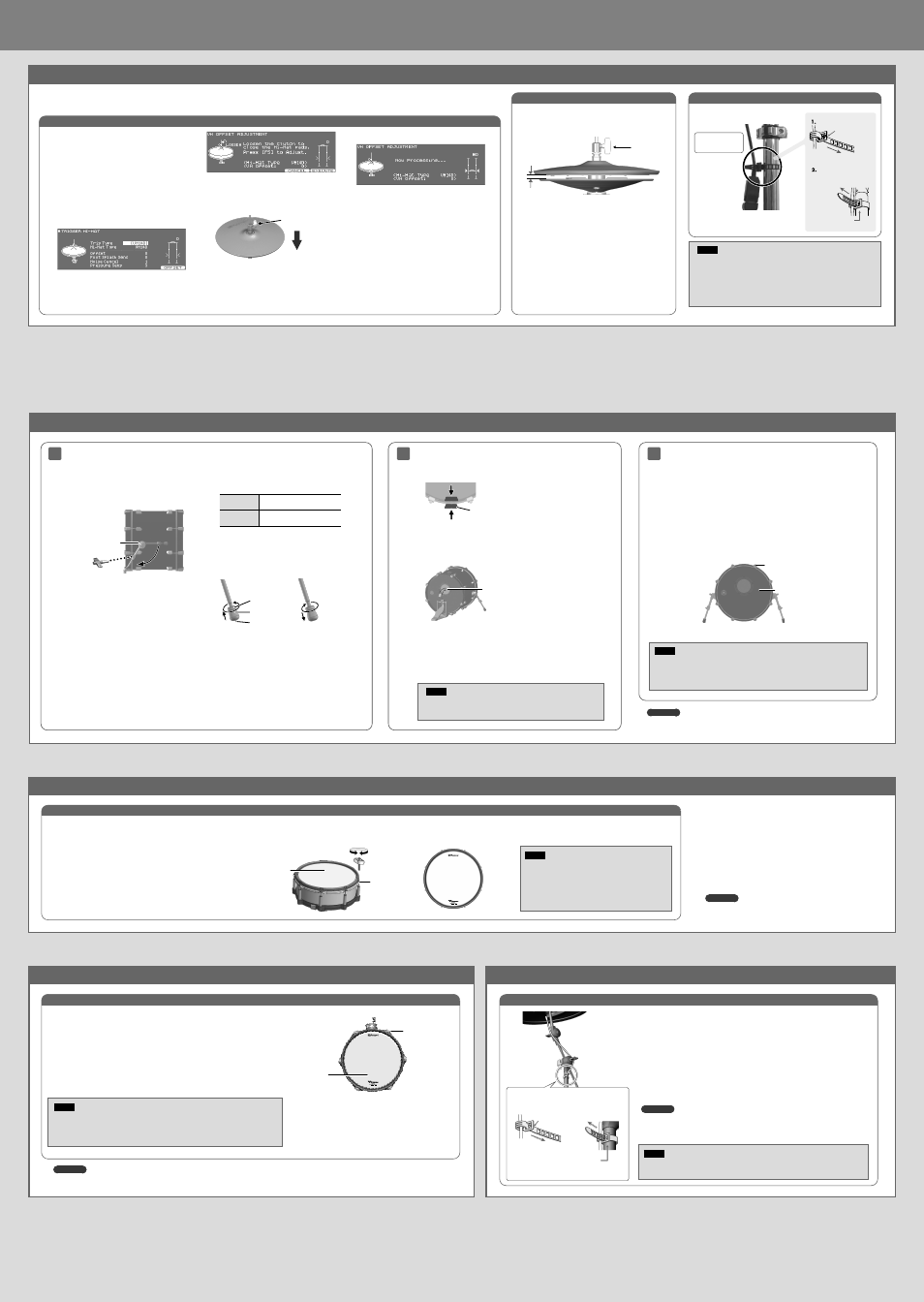
Detailed explanation of each part
Ã
Bass drum (KD-200)
Reference
For details on the Bass drum, refer to “KD-200 Owner’s Manual”.
1
2
NOTE
• Secure the kick pedal and KD-200 firmly in place.
• Take care not to pinch your fingers.
Extend the legs of the bass drum.
Attaching the kick pedal.
1.
Affix the wood hoop protectors to the position at which the kick
pedal is attached.
Wood hoop protectors
2.
Mount the kick pedal.
Adjust the location at which the kick pedal is attached so that the beater
strikes the center of the strike surface; then securely fasten the kick pedal
to the KD-200.
Beater must hit the center of
the striking surface
3.
After attaching the kick pedal, adjust the angle of the legs and the
length of the rods as necessary.
* A variety of commercially available beaters can be used, including felt,
plastic, or wood types.
However, if you use a felt beater, strike marks of the felt might remain on
the striking surface.
2.
Adjust the tip of the legs (spike/rubber)
appropriately for the surface on which you’re
placing the bass drum.
Spike
Soft floor
Carpet, etc.
Rubber
Hard floor
Wood flooring, concrete, etc.
If you loosen the foot nut and rotate the foot to raise
it, the spike will be exposed.
Tighten the foot nut to secure the position of the
foot.
Foot nut
Foot
Spike
Spike
Rubber
* The tip of the spike is sharp; handle it with care.
* Using the spike leg tips on wood flooring may
damage the floor; the rubber leg tips should be used
on wood flooring.
1.
Loosen the leg fastener knob, adjust the
angle of the leg, and then tighten the leg
fastener knob.
Using a drum key, adjust the length of the rods
so that the left and right are the same length.
Leg fastener knob
3
Adjusting the head tension
Adjust the tension of the batter head before you play the bass drum. You can
vary the strike response (playing feel) by adjusting the tension.
1.
Adjust each tension bolt little by little, working back and forth
across the head in the order shown in the illustration.
* Fully tightening a tension bolt at only a single location will produce
uneven tensioning, which will make it impossible to achieve correct strike
response and may also cause malfunctions.
2.
Adjust each tension bolt so that the head is tensioned evenly.
1
2
6
5
4
8
7
3
Batter head (inside)
Tension bolt
NOTE
Adjusting the head tension affects only the head response, and does not change the pitch of
the sound as it would on an acoustic drum.
Pitch adjustments are made by editing the sound in your drum sound module.
Ã
Snare (PD-140DS)
Reference
For details on the snare, refer to “PD-140DS Owner’s Manual”.
1.
Adjust each tuning bolt little by little, across the head as indicated in
the illustration.
Adjust the tension so that the pad responds to your strikes with the
appropriate feel.
2.
Make additional fine adjustments to the tension while you continue
checking the feel of the pad’s strike.
* Fully tightening a tension bolt at only a single location will produce uneven
tensioning, which will make it impossible to achieve correct strike response
and may also cause malfunctions.
1
2
6
5
4
8
7
3
Tighten
Loosen
Head
Tuning bolt
NOTE
Adjusting the head tension affects only the head response,
and does not change the pitch of the sound as it would on an
acoustic drum.
Pitch adjustments are made by editing the sound in your
drum sound module.
Adjusting the head tension
Ã
Crash cymbal (CY-16R-T) / (CY-14C-T)
Ã
Ride cymbal (CY-18DR)
Ã
Tom (PDA100 / PDA120 / PDA140F)
Reference
For details on the toms, refer to “PDA100/PDA120/PDA140F Owner’s Manual”.
Reference
For details on the cymbals, refer to “CY-16R-T/CY-14C-T Owner’s Manual” or “CY-18DR
Owner’s Manual”.
Adjusting the head tension
NOTE
Continuous playing may cause dis-coloration of the pad, but this will not affect the Pad’s function.
1.
Adjust each tuning bolt little by little, across the head as indicated in the
illustration.
Slightly stronger tension than the strike feel of an acoustic drum is appropriate.
2.
Make additional fine adjustments to the tension while you continue checking
the feel of the pad’s strike.
* Fully tightening a tension bolt at only a single location will produce uneven tensioning,
which will make it impossible to achieve correct strike response and may also cause
malfunctions.
Fixing the cables
2
1
5
3
4
6
Head
Tuning bolt
NOTE
Adjusting the head tension affects only the head response, and does not change the pitch of the
sound as it would on an acoustic drum.
Pitch adjustments are made by editing the sound in your drum sound module.
Secure the cable in place with
the cable tie
Leave some slack
in the cables
Be sure to make this
small plastic hook
visible from you.
Wind a cable tie
around the pipe and
tighten it in order to
not to slip.
Wind a cable tie around a cable.
Insert the small plastic hook
to a hole to secure the cable
to the cymbal arm.
Ã
Adjust the hi-hat (VH-14D)
When using the VH-14D, be sure to adjust the offset and hi-hat on the TD-27 after connecting.
This adjustment is required in order to correctly detect open, close, and pedal operations.
NOTE
* Continuous playing may cause dis-coloration of the pad, but this will not
affect the Pad’s function.
* See the VH-14D Owner’s Manual for details on the hi-hat.
Fixing the cables
Secure the cable in place
Secure the cable in place
with the cable tie
with the cable tie
Leave some slack in
the cable
Be sure to make this
small plastic hook
visible from
you.
Wind a cable tie around the
pipe and tighten it in order
not to slip.
Wind a cable tie around a
cable.
Insert the small plastic
hook to a hole to secure
the cable to the cymbal
arm.
1.
Press the [SYSTEM] button.
2.
Use the cursor buttons to select “TRIGGER”,
and then press the [ENTER] button.
3.
Use the cursor buttons to select “HI-HAT”, and
then press the [ENTER] button.
The TRIGGER HI-HAT screen appears.
* “VH-14D” is not shown as a Trig Type when the VH-
14D is not connected or if it is not assigned as the
hi-hat. In this case, connect the VH-14D and assign
it as the hi-hat.
4.
Press the [F5] (OFFSET) button.
The VH OFFEST ADJUSTMENT screen appears.
5.
Loosen the clutch screw of the top cymbal and
let it sit on the bottom cymbal.
* Do NOT touch the hi-hats or the pedal.
Clutch screw
6.
Press the [F5] (EXECUTE) button.
The “VH Offset” parameter is set automatically
(approx. 3 seconds).
7.
Press the [KIT] button to return to the DRUM
KIT screen.
Adjusting the offset
Adjusting the hi-hat
1.
Adjust the gap between the top cymbal and
bottom cymbal to a clearance of approximately 10
mm, then tighten the clutch screw.
Clutch screw
10 mm
* Although the gap can be adjusted to a clearance that makes
playing the hi-hat easier, setting too narrow or wide a gap can
cause improper function of the unit and prevent the hi-hat from
sounding as you intend. Setting the gap to 10 mm provides the
most natural feel when playing the VH-14D.
2.
Change the spring tension by adjusting the hi-hat
stand.
For instructions on adjusting the tension, refer to the
owner’s manual for your hi-hat stand.
* If the spring tension is too high or too low, the hi-hat may not
operate correctly and you might not be able to play the way you
intended.
* The tension may not be adjustable on some stands.