Controls and connections, Connecting, 1 connecting from source – Bowers & Wilkins CDA-16 16-Channel 8 Zone Distribution Amplifier User Manual
Page 4: 2 connecting to speakers
4
ENGLISH
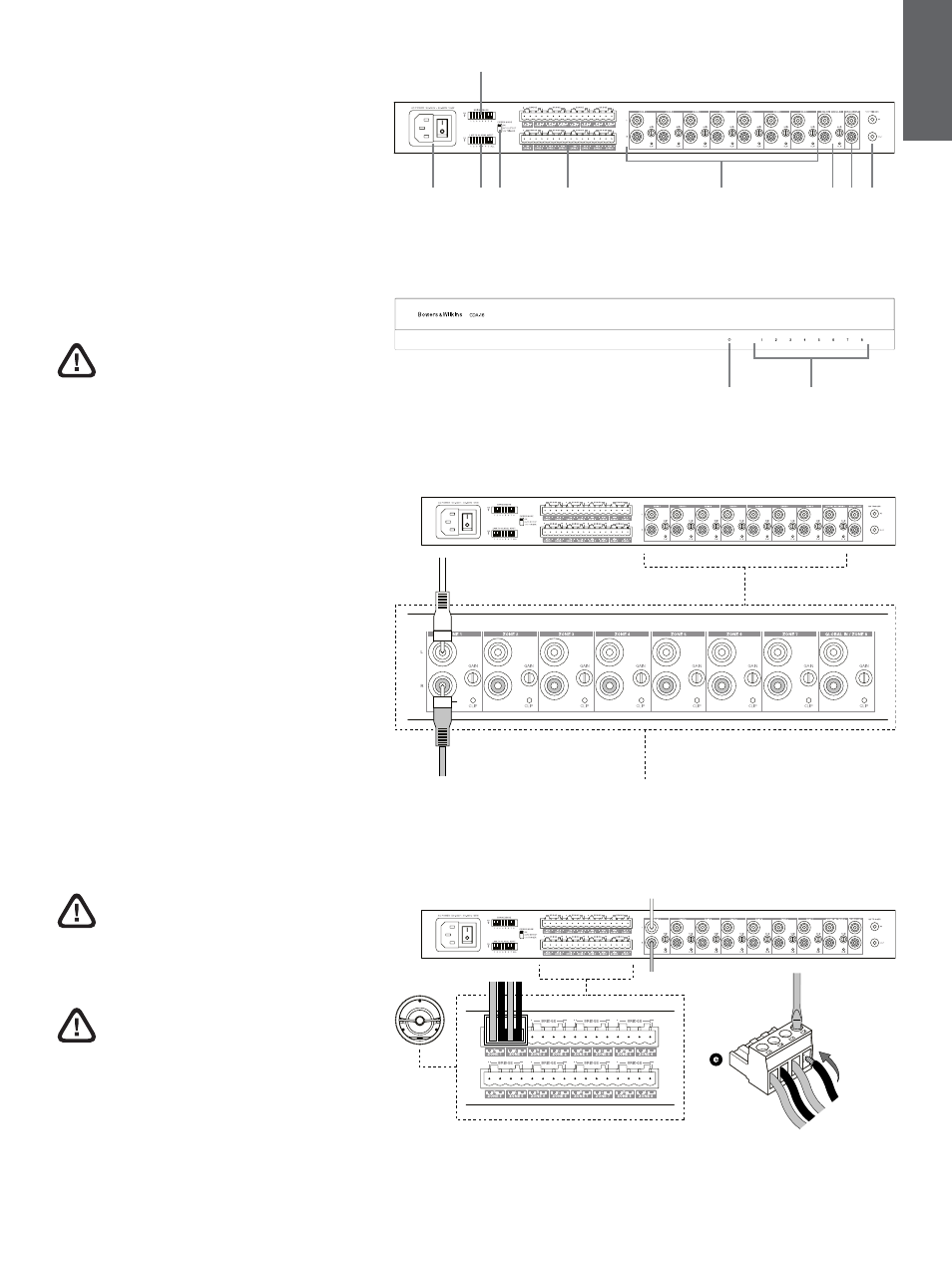
3. Controls and Connections
Rear panel sockets and switches
1. Power input socket (IEC C14)
2. Link to global input
3. Bridge mode
4. Power mode
5. Zone outputs
6. Zone 1 – 7 inputs
7. Zone 8 input / Global in
8. Global out
9. 12 V trigger in / out
Front panel controls
1. Power LED
2. Zone status LEDs
4. Connecting
Connecting speaker wires or input cables
while the amplifier is powered may cause
electrical shock and could damage the
amplifier. Unplug the power cord before making
connections.
4.1 Connecting from source
CDA-16 accepts stereo line-level audio connections
to its RCA Phono sockets. Each ZONE input will
pass amplified audio to the respective zone speaker
output. Alternatively, each ZONE can be linked
individually to the GLOBAL IN (shared with ZONE 8).
1. Connect the audio cable to the ZONE inputs
(1 – 8) RCA Phono inputs, see Diagram 6
2. (Optional) Connect the audio cable to GLOBAL
IN (ZONE 8) and link speaker outputs to the
GLOBAL IN by moving the dip switch up for
that zone to the ON position.
4.2 Connecting to speakers
CDA-16 can power eight stereo zones of audio
and has phoenix-style terminal blocks for speaker
connections. Speakers can also be wired to bridge
channels to increase the power available to the
speakers.
To connect stereo speakers:
1. Connect speaker cable to the phoenix
connector and reinsert into the amplifier,
see Diagram 7.
The common signal of these speaker
outputs must not be connected together
or to any other common signal. Do not
connect the L – and R – (negative) terminals
together. Doing so will result in a fault condition
and the amplifier will either shut down or not
work properly.
Check the polarity of the speakers and
wires before connecting to the amplifier.
Diagram 4
Rear panel
Diagram 5
Front panel
Diagram 6
Connecting from source
Diagram 7
Connecting to speakers
1
2
5
7 8
9
6
3
4
1
2
RCA