Setting power mode, Setting power mode 5 – Bowers & Wilkins CDA-16 16-Channel 8 Zone Distribution Amplifier User Manual
Page 5
5
ENGLISH
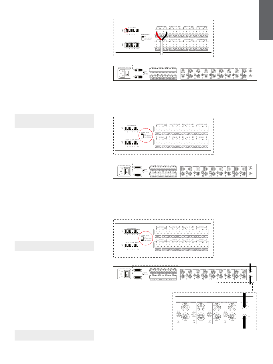
To connect bridged speakers, see Diagram 8:
1. Set the BRIDGE MODE dip switch if needed
for each zone by moving the dip switch up for
that zone to the ON position.
2. Connect + terminal from the speaker to the +
terminal of the right channel (R).
3. Connect the - terminal from the speaker to
the - terminal of the left channel (L) on
the amplifier.
The two terminals for a bridged pair of speakers area
marked by + BRIDGE –.
In bridge mode both amplifiers in the zone combine
to make a mono output of double the power. When
in bridge mode only the left channel RCA input to
the zone is active so please connect the input to
this jack.
Note: The minimum load impedance in bridge
mode is 8Ω. Connecting 4Ω loads may result in
lower output power, distortion and overheating.
5. Setting POWER MODE
CDA-16 can be set up to automatically power on
when needed. The POWER MODE switch, see
Diagram 9, allows CDA-16 to be powered on at all
times, turned on with a 12V trigger or turned on
when an audio signal is present at any audio input.
To set up CDA-16 to be always on:
1. Slide the POWER MODE switch to ON.
In this mode, CDA-16 will be always on unless the
power cord is unplugged or the power switch by the
power plug is toggled off.
To set up CDA-16 turn on by AUTO DETECT:
1. Slide the POWER MODE switch to
AUTO DETECT
In this mode, CDA-16 will turn on when an audio
signal is sensed on the audio input.
Note: Only the amplifier zone that senses audio
will turn on when in AUTO DETECT mode.
To set up CDA-16 to be controlled by a 12V trigger:
1. Slide the POWER MODE switch to
12V TRIGGER.
2. Connect the 12V trigger cable to the 3.5 mm
12V TRIGGER IN jack socket, see Diagram 10.
3. (Optional) Connect the 12V TRIGGER OUT jack
socket to another amplifier to link their power
control together.
In this mode, CDA-16 will turn on when a 12V signal
is present on the 12V Trigger Input. This 12V trigger
input can be wired to the 12V trigger output from an
audio matrix switch or a relay.
Note: All amplifier zones turn on when a 12V
trigger is received in 12V TRIGGER mode.
Diagram 8
Connecting bridged speakers
Diagram 9
Power mode switch
Diagram 10
Controlled by 12V trigger