GE 400 Series 30 Inch Freestanding Electric Range Installation Instructions User Manual
Page 3
5
3-WIRE INSTALLATION (cont.)
NOTE: ALUMINUM WIRING:
Aluminum
building wire may be used but it must be rated
for the correct amperage and voltage.
D. Replace wire cover on range back and
replace the screws that were removed
earlier. Make sure no wires are pinched
between cover and range back.
PROCEED TO STEP 6.
6
4-WIRE INSTALLATION
WARNING
The neutral wire of the supply
circuit must be connected to the neutral terminal
located in the lower center of the terminal block.
The power leads must be connected to the
lower left and the lower right terminals of the
terminal block. The grounding lead must be
connected to the range with the ground plate
and the green ground screw.
FOR POWER CORD INSTALLATION
A. Remove the 3 lower terminal screws from
the terminal block. Remove the ground
screw and ground plate and retain them.
Remove and discard the ground strap.
DO
NOT DISCARD ANY SCREWS.
B. Insert the one ground screw into the power
cord ground wire terminal ring, through the
ground plate and into the range.
C. Insert the 3
terminal screws
(removed earlier)
through each
power cord
terminal ring and
into the lower
terminals of the
terminal block.
Be certain that
the center wire
(white/neutral) is connected to the center
lower position of the terminal block. Tighten
screws securely into the terminal block.
6
4-WIRE INSTALLATION (cont.)
D. Replace wire cover on range back and
replace the screws that were removed
earlier. Make sure no wires are pinched
between cover and range back.
FOR CONDUIT INSTALLATION
A. Loosen the 3 lower terminal screws on the
terminal block. Strip wire to exposed tip
about 5/8” long.
B. Insert the center (white/neutral) wire tip
through the bottom center terminal block
opening. On certain models, the wire will
need to be inserted through the ground strap
opening and then into the bottom center
block opening. Insert the two side bare wire
tips into the lower left and the lower right
terminal block openings.
C. Tighten the screws until the wire is firmly
secured (35 to 50 inch-lbs.). Do not over-
tighten the screws.
NOTE: ALUMINUM WIRING:
Aluminum
building wire may be used but it must be rated
for the correct amperage and voltage.
Before–Power Cord and Conduit
Terminal
block
Neutral terminal
Ground
strap
Ground strap
Ground plate
Terminal
block
Ground
screw
After–Power Cord
Ground
plate
(grounding
to range)
After–Conduit
Terminal
block
Ground
plate
(grounding
to range)
Wire
tips
Ground
screw
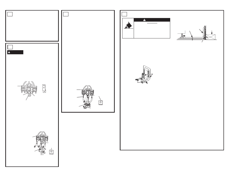
7
ANTI-TIP DEVICE INSTALLATION
To reduce the risk of tipping the range, the
range must be secured by a properly installed
anti-tip bracket. Remove any currently used
anti-tip bracket and install with the provided
anti-tip bracket.
1.
IMPORTANT
: Determine the final location
of the range before attempting to install the
bracket. Remove existing anti-tip bracket
from install space, if present.
a. Place the bracket on the floor with the
back edge against the rear wall. If the
range does not reach the rear wall, align
the back edge of the bracket with the rear
panel of the range in its final location.
If bracket does not touch the rear wall,
you MUST screw bracket to FLOOR as
described in Step 2.
b. Position the side of the bracket against
either the left or right cabinet. If there is
no adjacent cabinet, align the edge of
the bracket with the side panel of the
range in its final location. If the countertop
overhangs The cabinet, offset the bracket
from the cabinet by the amount of
overhang.
c. Mark the location for the pair of holes to be
used (see illustration above).
NOTE
: For FLOOR installation use either
Loc A or B. For REAR WALL installation
use Loc C.
2. The bracket must be screwed to either the
FLOOR or REAR WALL.
FLOOR Installation:
WOOD FLOOR:
Use the screws provided to
secure the bracket using the pair of marked
holes (either Loc A or B).
CONCRETE FLOOR:
Using a concrete
bit, drill a 5/32” pilot hole 2” deep into the
concrete at the center of each of the marked
holes (either Loc A or B). Use the screws
provided to secure the bracket into the floor.
REAR WALL Installation
:
Use the 2 screws provided to secure the
bracket using the pair of marked holes at
Loc C. The screws MUST enter into a wood
sill plate. If the wall contains any metal studs
or similar materials, then the floor must be
used.
3. To check if the bracket is installed and
engaged properly, look underneath the
range to see that the rear leveling leg is
engaged in the bracket. On some models,
the storage drawer or kick panel can be
removed for easy inspection. If visual
inspection is not possible, slide the range
forward, confirm the anti-tip bracket is
securely attached to the floor or wall, and
slide the range back so the rear leveling
leg is under the anti-tip bracket. If your
range is removed for cleaning, servicing,
or any reason, be sure the anti-tip device
is reengaged properly when the range is
replaced. Failure to take this precaution
could result in tipping of the range and can
result in death or serious burns to children
or adults. Never completely remove the
leveling legs or the range will not be secured
to the anti-tip device properly.
Anti-Tip
Bracket Kit
Included
Loc A
Loc B
Loc C
Two screws must enter floor
at Loc A or B or wall at Loc C.
Rear Wall
Screw must enter
wood or concrete
Attachment to Floor or Rear Wall
Wall Sill Plate
Screw must enter wood
Bracket
• A child or adult can tip the range and be killed.
• Install the anti-tip bracket provided with the unit
to the wall or floor.
• Engage the range to the anti-tip bracket by sliding the
range back such that the foot is engaged.
• Re-engage the anti-tip bracket if the range is moved.
• Failure to do so can result in death or serious burns
to children or adults.
Tip-Over Hazard
WARNING
- 600 Series 30 Inch Slide-In Electric Smart Range Installation Instructions 600 Series 30 Inch Freestanding Electric Smart Range Installation Instructions 500 Series 30 Inch Freestanding Electric Range Installation Instructions 400 Series 30 Inch Freestanding Electric Smart Range Installation Instructions 500 Series 30 Inch Slide-In Electric Range Installation Instructions