Operation – Ryobi RP4020 User Manual
Page 10
10 – English
OPERATION
Range
Introduction
Remark
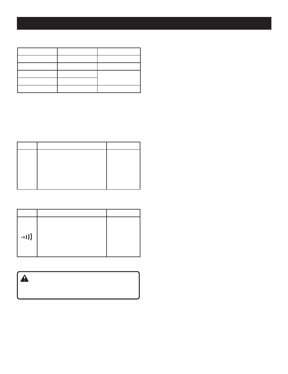
2V
The approximate forward volt-
age drop of the diode will be
displayed.
If the voltage drop is more than
2.0V, the display shows the over-
range indicator "OL".
Open Circuit
Voltage:
about 2.4V
Short Circuit
Current:
< 0.6mA
Overload Protection: 600V DC/AC rms
CONTINUITY TEST
Range
Introduction
Remark
The built-in buzzer will sound if
the resistance is less than about
20
Ω.
The buzzer will not sound if the
resistance is more than 150
Ω.
Open Circuit
Voltage:
about 0.45V
Overload Protection: 600V DC/AC rms
Overload Protection: 600V DC/AC rms
NOTE: Accuracy does not include error caused by the
capacitance of test lead and the meter. To reduce the error,
use Relative mode.
For range 100μF, wait about 30 seconds for reading to
settle.
DIODE TEST
WARNING:
Do not take readings unless the battery door is securely
closed.
USING RELATIVE MODE
See Figure 4, page 14.
Selecting Relative Mode stores the present reading as a
reference for subsequent measurements and sets the dis-
play to zero (0).
To enter Relative Mode, press the
REL▵ button. The
symbol "
"
will appear on the LCD display.
When you perform a new measurement, the display
shows the difference between the first (reference) and
the new measurement.
Press
REL▵ again to exit Relative mode and clear the
symbol.
NOTE: For capacitance measurements, the meter
remains in Autorange mode when you select Relative
mode. The actual capacitance to be measured must not
exceed 100μF even if you use Relative mode.
For other measurements which have both Autorange mode
and Manual Range mode, the meter changes to Manual
Range mode when you select Relative mode.
The actual value of the object under test must not exceed the
full-range reading of the selected range when you use Relative
mode. Use a higher measurement range if necessary.
MANUAL RANGING AND AUTORANGING
See Figure 4, page 14.
The meter defaults to Autorange mode in measurement
functions which have both Autorange mode and Manual
range mode. When the meter is in Autorange mode,
AUTO
is displayed.
Press the
RANGE button to enter the manual range mode.
The
AUTO symbol will disappear.
Each press of the
RANGE button increases the range.
When the highest range is reached, the meter wraps to
the lowest range.
To exit the manual range mode, press and hold down the
RANGE button for about 2 seconds. The meter will return
to Autorange mode and the symbol
AUTO will appear.
NOTE:
The
RANGE button is disabled in diode, continuity
and capacitance measurement functions.
DATA HOLD MODE
See Figure 4, page 14.
Press the
HOLD button to hold the present reading on
the display. The symbol
HOLD will appear on the display
as an indicator.
Press the button again to exit Data Hold mode. The sym-
bol
HOLD will disappear.
BUILT-IN BUZZER
When you press a button, the built-in buzzer will sound
a beep if the press is effective.
The buzzer will beep several times about 1 minute before
the meter turns off automatically, and give 1 long beep
before the meter turns off automatically.
Range
Resolution
Accuracy
40nF
0.01nF
±(4%+20)
400nF
0.1nF
±(3%+5)
4μF
0.001μF
±(4%+5)
40μF
0.01μF
100μF
0.1μF
±(8%+5)
CAPACITANCE