Through-hole vias – Altera MAX 10 FPGA User Manual
Page 6
1–2
Chapter 1: Overview
Board Component Blocks
MAX 10 FPGA (10M08S, 144-EQFP) Evaluation Kit
October 2014
Altera Corporation
User Guide
■
Push button and DIP switches
■
One reconfiguration push button (SW2)
■
One device-wide reset of all registers, push button (SW1)
■
User DIP switch (SW3)
■
Power
■
The board is powered by USB cable (from PC or wall jack)
■
One green power-on LED (D6)
■
Probe points for manual, multi-meter measurement of current to calculate
power consumption (TP2 - TP5) or to verify voltages on the selected internal
nodes (TP1, TP6 - TP9)
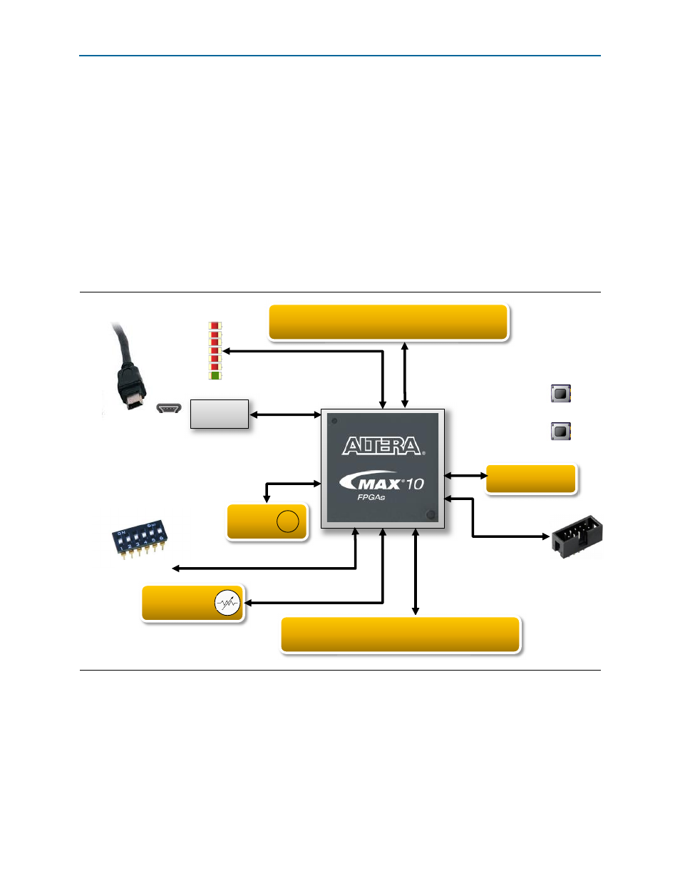
Figure 1–1. Example MAX 10 Evaluation Kit Block Diagram
Push Button
Push Button
10M08S
E144
Through-hole vias
* Potentiometer
Oscillator
~
JTAG
LEDs
To power source
Mini-USB
B
Enpirion
Supplies
Arduino UNO R3
connectors
DIP switch
Through-hole vias
* Customer must purchase and install.