Cascaded decoding –7 decoding latency –7, Cascaded decoding, Decoding latency – Altera 8B10B Encoder/Decoder MegaCore Function User Manual
Page 25
Chapter 3: Specifications
3–7
Functional Description
May 2011
Altera Corporation
8B10B Encoder/Decoder MegaCore Function User Guide
When the receiver detects a disparity error, the
rderr
signal is asserted.
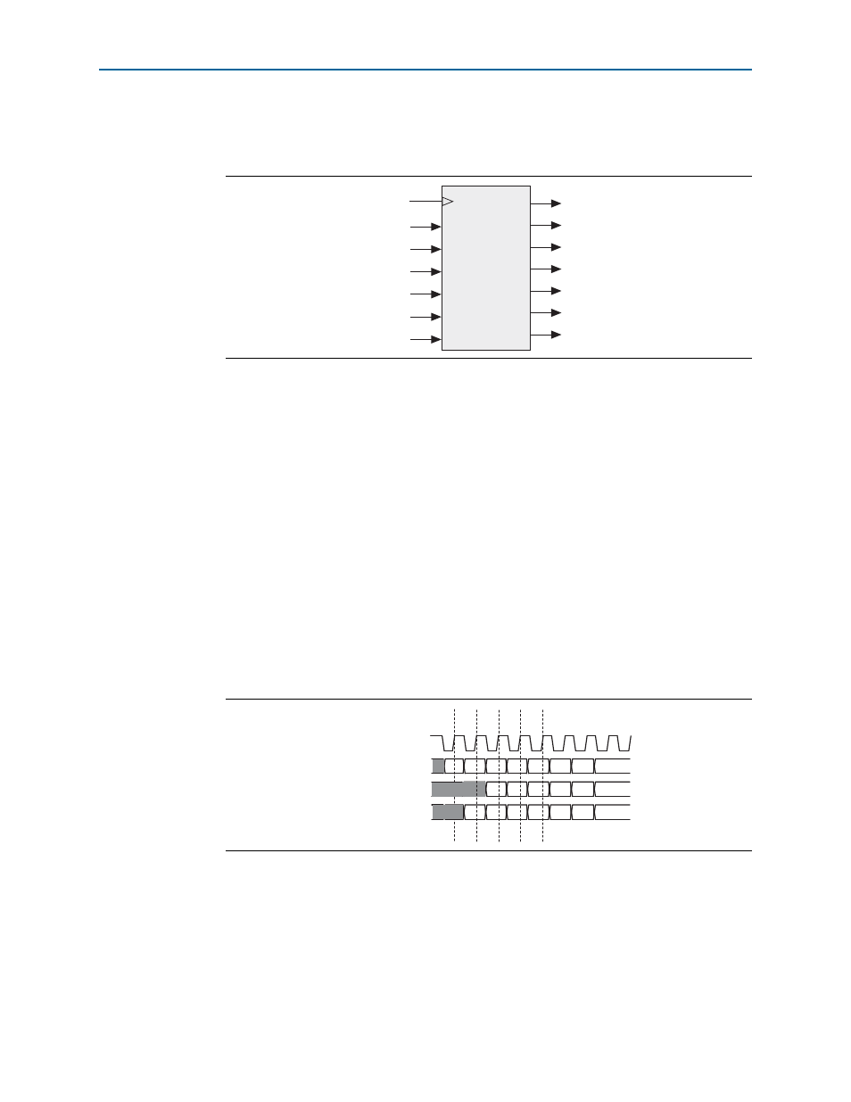
Figure 3–7
shows a block diagram of the decoder.
Cascaded Decoding
Two decoders can be cascaded to decode two words simultaneously. The decoders are
cascaded—in a similar fashion as the encoders—by connecting the
rdcascade
output
of the first decoder to the
rdin
input of the second decoder, and by connecting the
rdout
output of the second decoder to the
rdin
input of the first decoder. The
rdforce
inputs of both decoders must be tied high.
To enable cascaded decoding, the data paths fed by the
rdin
and
rdforce
inputs are
not pipelined. If these inputs are to be used in non-cascaded decoders, they should be
delayed by one clock cycle with respect to their corresponding
datain
and
kin
inputs.
Decoding Latency
The decoder is pipelined, thus it takes two clock cycles for a character to be decoded.
The decoded value—corresponding to the value of
datain
sampled by the decoder on
rising edge
n
—is output shortly after rising edge
n+1
, and is available to be sampled
on the rising edge of clock cycle
n+2
. (See
Figure 3–6 on page 3–6
).
Figure 3–7. Decoder
Figure 3–8. Decoder Timing Diagram
clk
reset_n
idle_del
ena
datain [9:0]
valid
dataout [7:0]
kout
kerr
rderr
rdin
rdforce
rdout
rdcascade
clk
datain, ena
rdforce, rdin
a
b
c
d
e
f
g
a
b
c
d
e
a
b
c
d
e
f
n+1
n
n+2 n+3
dataout, kout
kerr, rdout, rderr