Electric parameters and design guidelines, Decoupling capacitor (high/mid frequency), Decoupling capacitor (bulk) – Altera Device-Specific Power Delivery Network User Manual
Page 19
Chapter 1: User Guide for the Device-Specific Power Delivery Network (PDN) Tool
1–15
Major Tabs of the PDN Tool
September 2012
Altera Corporation
Device-Specific Power Delivery Network (PDN) Tool User Guide
Electric Parameters and Design Guidelines
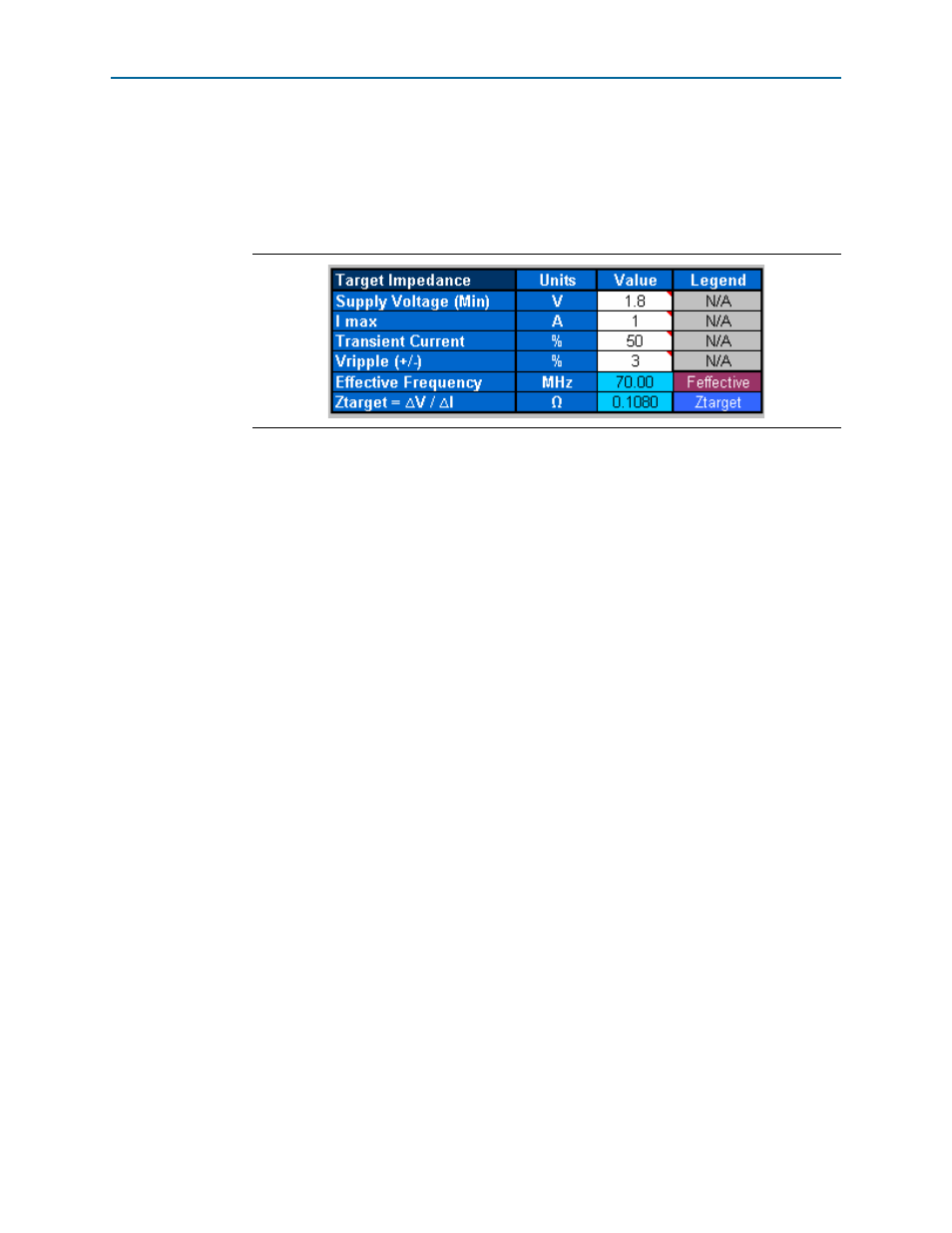
The PDN tool calculates Z
TARGET
based on the user inputs in this field. The PDN tool
also displays F
EFFECTIVE
that is derived based on the PCB stack-up and power rail
information (
). The details regarding the calculation procedure are
described in
and
You need to enter information for:
■
Power Supply Voltage (min)
■
I
MAX
■
Transient Current (%)
■
Allowable Voltage Ripple Percentage (±)
The tool then calculates Z
TARGET
based on the user input from related fields and
displays the results in the column below.
Decoupling Capacitor (High/Mid Frequency)
You can select the various decoupling capacitors, both two-terminal and X2Y types,
based on footprint, layer, and orientation to meet the target impedance for the mid to
high frequency. The capacitance value for the X2Y capacitor may be different from
that of the two-terminal capacitor. A warning message of "Wrong Footprint" is
displayed if you choose a wrong combination of capacitance and footprint. The VOE
and VOS option do not affect the mounting inductance for X2Y type capacitors
because their via locations are symmetric. You also have the option of defining custom
capacitor values (User1, ..., User4) needed for high/mid frequency decoupling
specific to the design. You cannot change the capacitor parasitics (ESR and ESL) in this
tab. This can only be done in the Library tab.
Decoupling Capacitor (Bulk)
You can select the desired bulk capacitors based on the footprint for the low to mid
frequency decoupling need. You can only change the parasitics of the bulk decoupling
capacitors and define the mounting inductance specific to the design in the Library
tab. You also have the option of defining custom capacitor values (User5 and User6)
for low/mid frequency decoupling specific to the design.
Figure 1–11. Electric Parameters and Design Guidelines