Derive decoupling in a single-rail scenario, Derive decoupling in a single-rail scenario –19 – Altera Device-Specific Power Delivery Network User Manual
Page 23
Chapter 1: User Guide for the Device-Specific Power Delivery Network (PDN) Tool
1–19
Design PCB Decoupling Using the PDN Tool
September 2012
Altera Corporation
Device-Specific Power Delivery Network (PDN) Tool User Guide
In the pre-layout phase, you can ignore the Plane Cap and Cap Mount tabs and go
directly to the Library tab when you do not have the layout information.
shows the fields in the Library tab that you will use to enter the various parameters. If
available, enter the values shown in
in the Library tab. To use the default
values, go directly to the Decap Selection tab to begin the analysis.
Derive Decoupling in a Single-Rail Scenario
A power supply connects to only one power rail on the FPGA device in a single-rail
scenario. The PDN noise is created by the transient current of the single rail. You
determine Z
TARGET
and F
EFFECTIVE
based on the parameters related to the selected rail
only.
You must follow the steps below to derive the desired capacitor combination:
1. Select the device/power rail to work with.
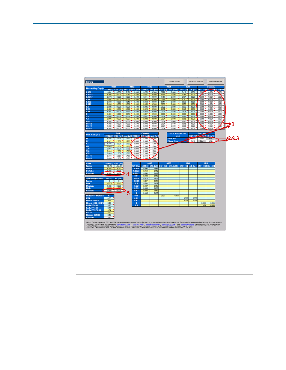
Figure 1–14. Library Tab Fields
Notes to
The numbers correspond to the following steps 1, 2, 3, 4, 5.
(1) Enter the ESR, ESL, and Lmnt values for the capacitors under the Custom field.
(2) Enter the effective BGA via (loop) parasitics for the power supply being decoupled.
(3) Enter the plane capacitance seen by the power/ground plane pair on the board for the power supply under Plane Cap.
(4) Enter the VRM parasitics, if available, under the Custom row.
(5) Enter the effective spreading inductance seen by the decoupling capacitors in Custom row.