Masterblaster connections, Masterblaster connections –3, Header & plug connections –3 – Altera MasterBlaster Serial/USB User Manual
Page 15
Chapter 2: MasterBlaster Serial/USB Communications Cable Data Sheet
2–3
Functional Description
© July 2008
Altera Corporation
MasterBlaster Serial/USB Communications Cable User Guide
MasterBlaster Connections
The MasterBlaster cable connects to a computer through a serial or USB port and
connects to the circuit board through a standard 10-pin female connector. Data is
downloaded from the serial or USB port through the MasterBlaster cable to the circuit
board through the connections discussed in this section.
Header & Plug Connections
The 9-pin male D-type connector connects to an RS-232 port with a standard serial
cable. See
.
1
The USB connector can be used with any standard USB cable.
f
For more information on 9-pin versus 25-pin serial connectors, search for “9-pin or 25-
pin serial connectors” in the Altera solutions database
The 10-pin female plug connects to a 10-pin male header on the circuit board
containing the target device(s).
shows the dimensions of the female plug.
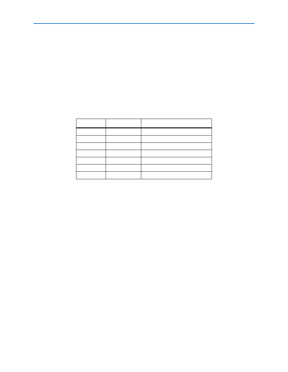
Table 2–1. MasterBlaster 9-Pin Serial D-Type Connector Pin-Outs
Pin
Signal Name
Description
2
rx
Receive data
3
tx
Transmit data
4
dtr
Data terminal ready
5
GND
Signal ground
6
dsr
Data set ready
7
rts
Request to send
8
cts
Clear to send