Led status, Operating conditions, Circuit board header connection –5 – Altera MasterBlaster Serial/USB User Manual
Page 17: Led status –5, Operating conditions –5, Figure 2–1: 10-pin male header dimensions -5, Table 2–1: led status indicator -5
Chapter 2: MasterBlaster Serial/USB Communications Cable Data Sheet
2–5
Operating Conditions
© July 2008
Altera Corporation
MasterBlaster Serial/USB Communications Cable User Guide
When 5.0- or 3.3-V power is not available on the circuit board, the MasterBlaster cable can be
powered by either DC power or the USB cable.
1
For the MasterBlaster cable’s output drivers, connect the circuit board’s V
CC
and
ground to the MasterBlaster cable’s VCC, VIO, and GND pins.
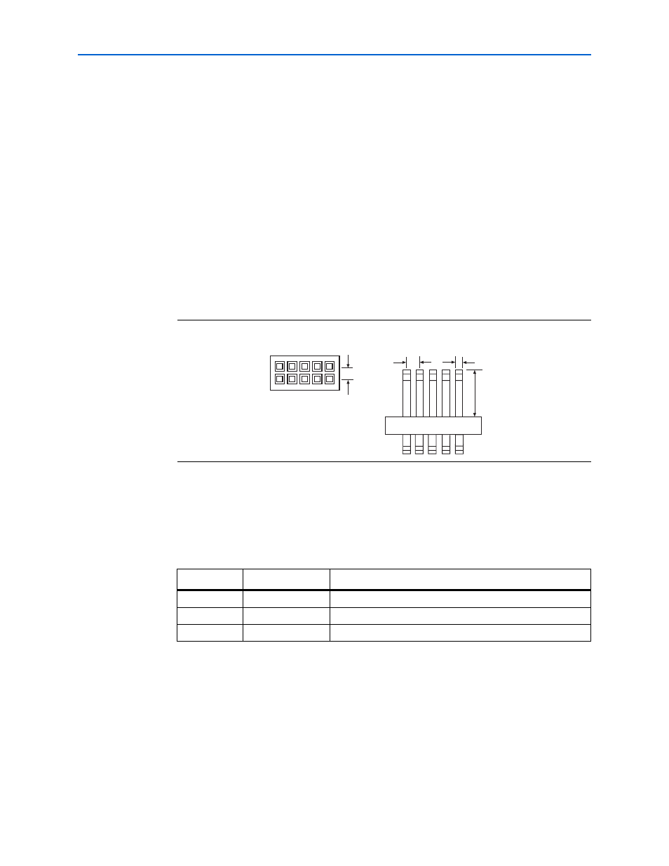
Circuit Board Header Connection
The MasterBlaster cable’s 10-pin female plug connects to a 10-pin male header on the
circuit board. The 10-pin male header has two rows of five pins, which are connected
to the device’s programming or configuration pins.
shows the dimensions
of a typical 10-pin male header.
1
Although a 10-pin surface mount header can be used for the JTAG, AS or PS
download cable, Altera recommends using a through-hole connector due to the
repeated insertion and removal force needed.
LED Status
The purpose of the LED indicator lights located on the MasterBlaster download cable
is to provide information about the status of the MasterBlaster cable.
lists
the indicator and status of the MasterBlaster cable.
Operating Conditions
through
summarize the absolute maximum ratings, recommended
operating conditions, and DC operating conditions for the MasterBlaster cable.
Figure 2–1. 10-Pin Male Header Dimensions
0.025 Sq.
0.235
0.100
Side View
0.100
Top View
Table 2–1. LED Status Indicator
Color
Blink Frequency
Description
Green
Slow
Cable ready
Green
Fast
Performing a logic analysis
Amber
Slow
Programming in progress