Powering the masterblaster cable –4, Powering the masterblaster cable – Altera MasterBlaster Serial/USB User Manual
Page 16
2–4
Chapter 2: MasterBlaster Serial/USB Communications Cable Data Sheet
Functional Description
MasterBlaster Serial/USB Communications Cable User Guide
© July 2008
Altera Corporation
identifies the 10-pin female plug’s pin names for the corresponding
download mode.
Powering the MasterBlaster Cable
The MasterBlaster cable can receive power from the following sources:
■
5.0- or 3.3-V circuit boards
■
DC power supply
■
5.0 V from the USB cable
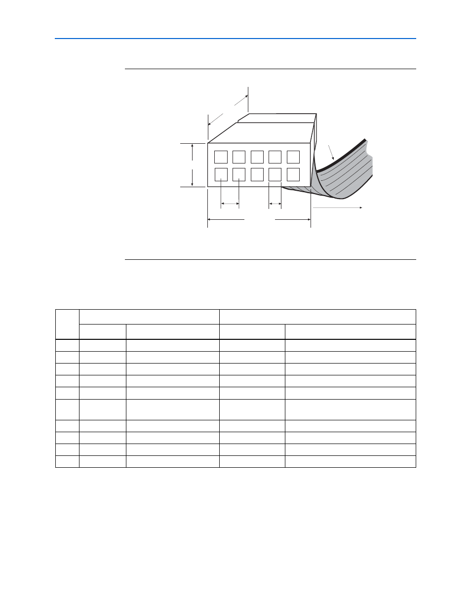
Figure 2–2. MasterBlaster 10-Pin Female Plug Dimensions
Dimensions are shown in inches. The spacing between pin centers is 0.1 inches.
0.250 Typ.
0.700 Typ.
0.425 Typ.
0.100 Sq.
2
3
4
6
7
8
9
0.025 Sq.
Color Strip
1
5
10
Table 2–2. MasterBlaster Female Plug’s Pin Names & Download Modes
Pin
PS Mode
JTAG Mode
Signal Name
Description
Signal Name
Description
1
dclk
Clock signal
tck
Clock signal
2
gnd
Signal ground
gnd
Signal ground
3
CONF_DONE
Configuration control
tdo
Data from device
4
V
CC
Power supply
V
CC
Power supply
5
nCONFIG
Configuration control
tms
JTAG state machine control
6
V
IO
Reference voltage for
MasterBlaster output driver
V
IO
Reference voltage for MasterBlaster output
driver
7
nstatus
Configuration status
–
No connect
8
–
No connect
–
No connect
9
data0
Data to device
tdi
Data to device
10
gnd
Signal ground
gnd
Signal ground