Low power demonstration, Figure 2–4 – Altera MAX II User Manual
Page 20
2–12
Development Kit Version 1.1.0
Altera Corporation
MAX II Development Kit Getting Started User Guide
July 2005
Demo Designs
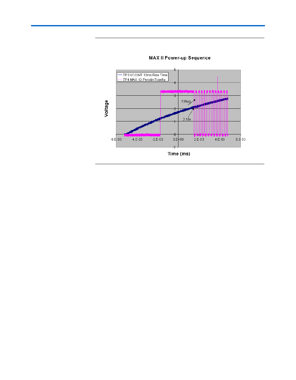
Figure 2–4. Digital Oscilloscope Image of V
CCINT
and MAX I/O During Power-Up
Low Power Demonstration
MAX II devices consume very little power, making them ideal for use in
systems where power is at a premium. The MAX II development board is
equipped with two current sense circuits that allow users to measure the
power consumed by the MAX II device at different design densities and
toggle rates.
This demonstration provides an easy way to increase the number of
registers in the design and the rate at which they are toggling. This gives
you some understanding of the power that a MAX II device requires. The
demonstration measures the current drawn by V
CCINT
as the number of
toggling registers (and the rate at which they toggle) is increased or
decreased.
To calculate the power drawn, multiply the number of toggling registers
by the voltage supply of V
CCINT
(if the shunt on J9 is in place,
V
CCINT
= 2.5 V; if the shunt is off, V
CCINT
= 3.3 V). Note that the power can
always be calculated by measuring the voltage across the current sense
resistors and then using Ohm’s Law to calculate the current. The V
CCINT
current is measured across two parallel 0.33 ohm resistors (R109 and
R113). You can measure the voltage across either one of these resistors and
then divide that by 0.165 ohms (the two 0.33 ohm resistors are in parallel
for a total resistance of 0.165). Use Ohm’s Law to calculate the current and