Configuration, status, and setup elements, Configuration, Cpld configuration over embedded usb-blaster – Altera MAX V CPLD Development Board User Manual
Page 11: Configuration, status, and setup elements –5, Configuration –5, Cpld configuration over embedded usb-blaster –5
Chapter 2: Board Components
2–5
Configuration, Status, and Setup Elements
January 2011
Altera Corporation
MAX V CPLD Development Board Reference Manual
Configuration, Status, and Setup Elements
This section describes the board's configuration, status, and setup elements.
Configuration
The MAX V CPLD development board supports the following device configuration
methods:
■
Embedded USB-Blaster is the default method for configuring the CPLD at any
time using the Quartus II Programmer in JTAG mode with the supplied USB cable.
■
External USB-Blaster for configuring the CPLD using a JTAG connector. To use this
optional method to configure the CPLD, you have to mount the JTAG connector or
header to the back of the board.
CPLD Configuration over Embedded USB-Blaster
The USB-Blaster is implemented using a USB Type-B connector (J4), a FTDI USB 2.0
PHY device (U3), and an Altera MAX II CPLD EPM240M100 (U4). This allows the
configuration of the MAX V CPLD using a USB cable which connects between the
USB port on the board (J4) and a USB port of a PC running the Quartus II software.
The JTAG chain is normally mastered by the embedded USB-Blaster found in the
MAX
II CPLD EPM240M100.
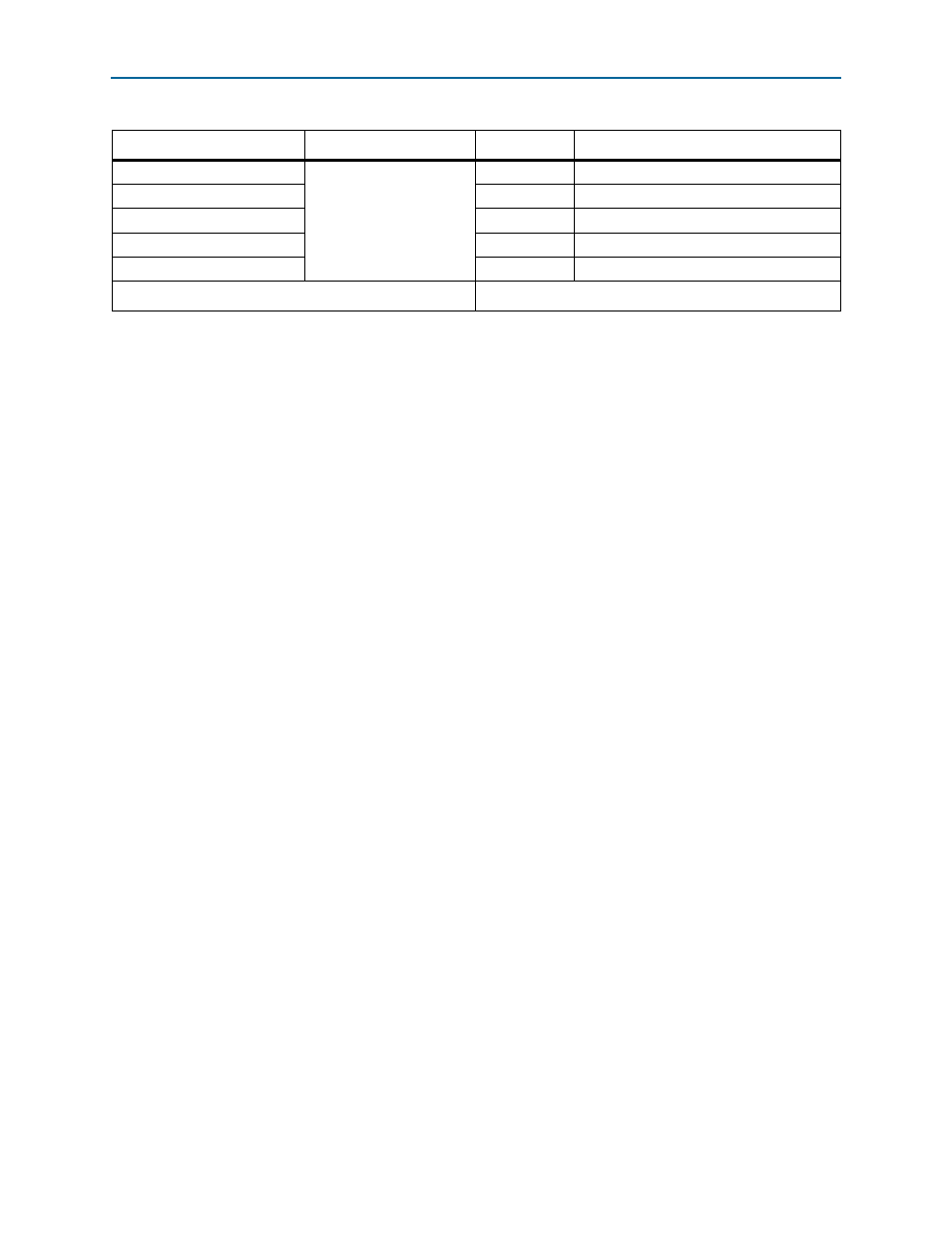
Push-Buttons
3.3-V CMOS
2
Push-button 2: Dev_CLRn
User LEDs
2
—
I
2
C EEPROM
2
—
SPI EEPROM
4
—
Clock
1
—
Device I/O Total:
109/159
Table 2–4. MAX V CPLD Device I/O Pin Count and Usage (Part 2 of 2)
Function
I/O Standard
I/O Count
Special Pins