Board overview, Board overview –2, Figure 2–1 – Altera MAX V CPLD Development Board User Manual
Page 8: Table 2–1
2–2
Chapter 2: Board Components
Board Overview
MAX V CPLD Development Board Reference Manual
January 2011
Altera Corporation
Board Overview
This section provides an overview of the MAX V CPLD development board,
including an annotated board image and component descriptions.
provides an overview of the development board features.
describes the components and lists their corresponding board references.
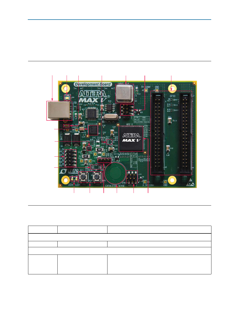
Figure 2–1. Overview of the MAX V CPLD Development Board Features
MAX V
CPLD
(U5)
10-MHz Single-Ended
External Oscillator
(J1)
User
LEDs
(D7, D8)
GPIO Headers
(J6, J7)
USB Type-B
Connector (J4)
Motor Control
Header 1
(J5)
Power LED
(D1)
User
Push-Button
Switches (S1, S2)
MAX II CPLD
EPM240M100C4N
(For embedded
USB-Blaster) (U4)
Motor Control
Header 2
(J10)
Speaker
Header
(J9)
Footprint for
I
2
C EEPROM
(U6)
Footprint for
SPI EEPROM
(U8)
Power
Regulator
(U7)
USB LED
(D3)
Capacitor
Sense Button
(CPB1)
VAR_VCCIO
Voltage Output
Selection Jumper
(U7)
Table 2–1. MAX V CPLD Development Board Components (Part 1 of 2)
Board Reference
Type
Description
Featured Device
U5
CPLD
MAX V 5M570ZF256C5N, 256-pin FBGA.
Configuration, Status, and Setup Elements
J4
USB Type-B connector
Connects the USB cable to the computer to enable embedded
USB-Blaster JTAG. The connector also supplies power to the board
through a USB cable when the cable is connected to a PC USB slot at
the other end.