Off-chip eeprom, I2c eeprom, Off-chip eeprom –14 – Altera MAX V CPLD Development Board User Manual
Page 20: C eeprom
2–14
Chapter 2: Board Components
Off-Chip EEPROM
MAX V CPLD Development Board Reference Manual
January 2011
Altera Corporation
lists the user-defined LED component reference and the manufacturing
information.
Off-Chip EEPROM
This section describes the board's EEPROM interface support and also their signal
names, types, and connectivity relative to the MAX V CPLD device. The board
include footprints for you to mount the following EEPROM device:
■
I
2
C EEPROM
■
SPI EEPROM
1
The MAX V CPLD development board only provide the EEPROM device footprints.
However, the board test system EEPROM function is developed based on the
EEPROM components described in this section.
I
2
C EEPROM
Board reference U6 is a footprint to mount an I
2
C EEPROM device onto the
development board.
lists the I
2
C EEPROM device pin assignments, signal names, and functions.
The signal names and types are relative to the MAX V CPLD device in terms of I/O
setting and direction.
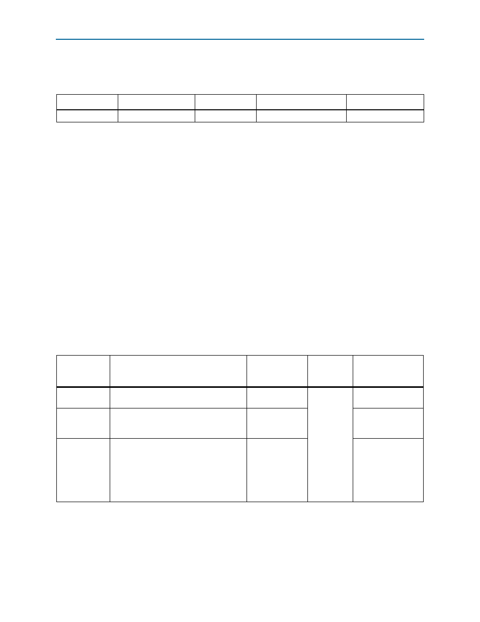
Table 2–18. User-Defined LED Component Reference and Manufacturing Information
Board Reference
Device Description
Manufacturer
Manufacturer Part Number
Manufacturer Website
D7, D8
Green LEDs
Lumex, Inc.
SML-LX1206GC-TR
Table 2–19. I
2
C EEPROM Pin Assignments, Schematic Signal Names, and Functions
Board
Reference
Description
Schematic Signal
Name
I/O Standard
MAX V CPLD Device
Pin Number
U6.1
Clock to synchronize the data transfer to and
from the device.
I2C_PROM_SCL
3.3-V
T13
U6.2
Bidirectional serial data pin to transfer
addresses and data into and out of the
device.
I2C_PROM_SDA
R13
U6.5
Write-protect pin.
■
Tied to V
ss
: Normal operation (read or
write to the entire memory of 000-3FF).
■
Tied to V
cc
: Write operation disabled (the
entire memory is write-protected). Read
operation is not affected.
I2C_PROM_WP
—