Altera Transceiver Signal Integrity Development Kit, Stratix V GX Edition User Manual
Page 49
Chapter 2: Board Components
2–41
Power Supply
July 2012
Altera Corporation
Transceiver Signal Integrity Development Kit
Stratix V GX Edition Reference Manual
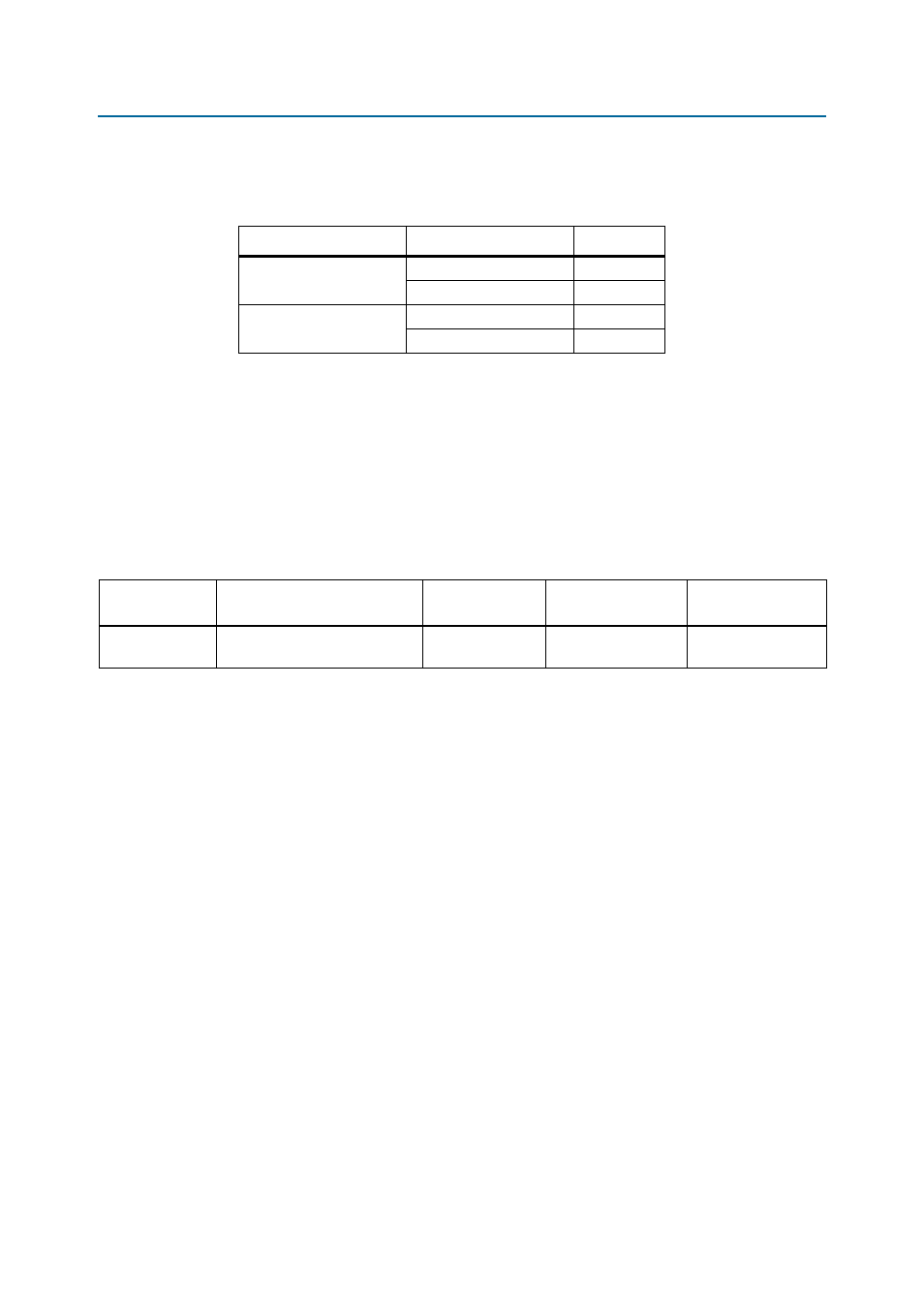
lists the VCCRT_GXB and VCCA_GXB voltage rails and their voltage level
depending on the switch position.
1
If the board is powered off and powered on again with SW2 in the open position, the
voltages for VCCRT_GXB and VCCA_GXB voltage rails read 0.90 V and 2.5 V respectively
and will not come up to the proper levels. This is due to the LTC2978 device trying to
adjust these rails to their programed values, which it cannot due to the switch
position of SW2. The work around to this issue is to set switch SW2 in the close
position at power up.
lists the power monitor devices component reference and manufacturing
information.
Table 2–42. Voltage Level Setting
Switch (Position 1 and 2)
Schematic Net Name
Voltage (V)
Close (Default)
VCCRT_GXB
1.0
VCCA_GXB
3.0
Open
VCCRT_GXB
0.9
VCCA_GXB
2.5
Table 2–43. Power Measurement ADC Component References and Manufacturing Information
Board Reference
Description
Manufacturer
Manufacturing
Part Number
Manufacturer
Website
U10, U11
IC, power supply monitor
w/EPROM, octal PMBUS
Linear Technology
LTC2978CUP#PBF