Sd card interface (j7), Sd card interface (j7) –16 – Altera Santa Cruz User Manual
Page 22
2–16
Chapter 2: Board Components
SD Card Interface (J7)
Santa Cruz, USB, MICTOR, SD Card HSMC Reference Manual
© December 2008 Altera Corporation
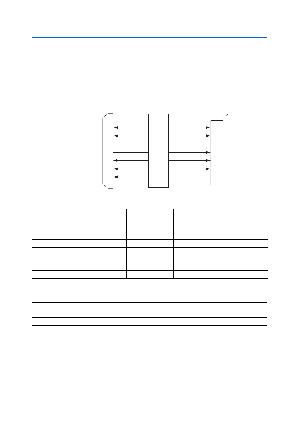
SD Card Interface (J7)
The THDB-SUM board has an SD card socket that can be accessed as an optional
external memory in both SPI and 1-bit SD mode.
shows the pin-outs of
the SD card socket.
lists the detailed pin mapping between the SD card
socket and the HSMC connector.
lists the SD card socket board reference and manufacturing information.
Figure 2–14. SD Card Socket and HSMC Connector Block Diagram
Level
Shifters
(U9)
HSMC Connector
(J1)
9
LF_DAT2
LF_DAT3
1
2
LF_CMD
LF_CLK
5
LF_DAT0
7
LF_DAT1
8
LF_WPn
11
SD_DAT2
SD_DAT3
SD_CMD
SD_CLK
SD_DAT0
SD_DAT1
SD_WPn
DAT2
DAT3
CMD
CLK
DAT0
DAT1
WPn
SD Card Socket
(J7)
Table 2–14. SD Card Socket (J7) Pin Assignments
SD Card Socket
Pin Number
SD Card Socket
Signal Name
HSMC Pin Number
HSMC Signal Name
HSMC Pin Name
1
LF_DAT3
42
SD_DAT3
HSMC_D1
2
LF_CMD
47
SD_CMD
HSMC_TX_P0
5
LF_CLK
43
SD_CLK
HSMC_D2
7
LF_DAT0
41
SD_DAT0
HSMC_D0
8
LF_DAT1
39
SD_DAT1
HSMC_CLKOUT0
9
LF_DAT2
44
SD_DAT2
HSMC_D3
11
LF_WPn
40
SD_WPn
HSMC_CLKIN0
Table 2–15. SD Card Socket Board Reference and Manufacturing Information
Board Reference
Description
Manufacturer
Manufacturing
Part Number
Manufacturer
Website
J7
SD Card Socket
Leamax Enterprise
9301S-090001