Altera Santa Cruz User Manual
Page 9
Chapter 2: Board Components
2–3
Board Overview
© December 2008 Altera Corporation
Santa Cruz, USB, MICTOR, SD Card HSMC Reference Manual
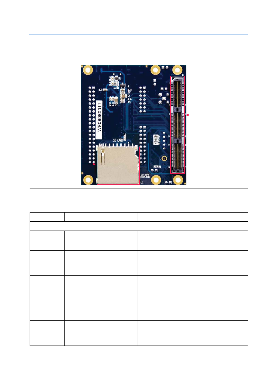
shows the back view of the THDB-SUM board.
describes the components and lists their corresponding board references.
Figure 2–2. THDB-SUM Board—Back View (HSMC Connector View)
SD Card
Socket (J7)
HSMC
Connector (J1)
Table 2–1. THDB-SUM Board (Part 1 of 2)
Board Reference
Name
Description
Components and Interfaces
J1
HSMC connector
Expansion connector used to interface with Altera starter and
development boards.
J2
MICTOR connector
Used for logic analysis.
J3, J4, and J5
Santa Cruz connectors
Expansion connectors used to connect with Santa Cruz
interface.
J6
SMA connector
SMA connector that allows the provision of an external clock
input.
J7
SD card socket
Used as optional external memory in both serial peripheral
interface
(SPI) and 1-bit SD mode.
J8
Mini USB AB type receptacle connector
Provide USB interface to the HSMC interface host board.
JP0
JTAG TDI/TDO loopback header
Used to either include or bypass daughtercard in the JTAG
chain by connecting TDI to TDO when jumper is inserted.
JP1
USB/Santa Cruz function select header
Used to select between USB functionality or full Santa Cruz
header functionality.
JP2
USB Host/Peripheral mode
configuration header
When closed, selects USB in host mode.
JP3
HSMC logic level configuration header
When open, selects 2.5 V HSMC source voltage.
When closed, selects 3.3 V.