Sma connector (j6), I2c serial eeprom (u10), Sma connector (j6) –17 i – Altera Santa Cruz User Manual
Page 23: C serial eeprom (u10)
Chapter 2: Board Components
2–17
SMA Connector (J6)
© December 2008 Altera Corporation
Santa Cruz, USB, MICTOR, SD Card HSMC Reference Manual
SMA Connector (J6)
The THDB-SUM board provides an SMA connector (J6) for external clock input.
shows the pin assignments of the SMA connector.
lists the SMA connector board reference and manufacturing information.
I
2
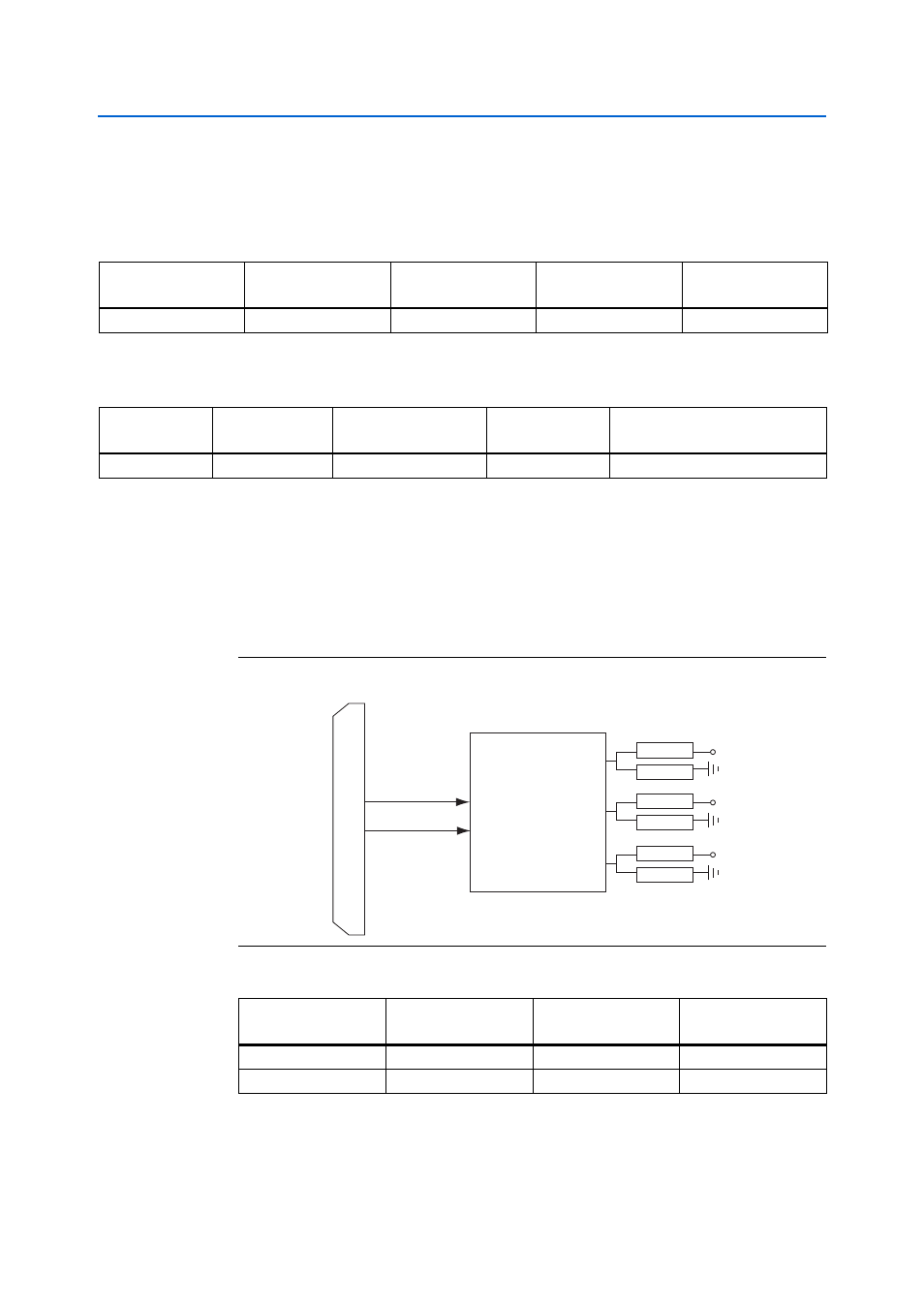
C Serial EEPROM (U10)
The THDB-SUM board provides an EEPROM (U10) which can be configured by the
I
2
C interface. The size of the EEPROM is 2 Kbits and it can store board information or
user’s data.
shows the pin-outs of the EEPROM.
lists the
detailed pin mapping between the EEPROM and the HSMC connector.
Table 2–16. SMA Connector (J6) Pin Assignments
SMA Connector
Pin Number
SMA Connector
Signal Name
HSMC Pin Number
HSMC Signal Name
HSMC Pin Name
1
EXT_CLK
96
EXT_CLK
HSMC_CLKIN_P1
Table 2–17. SMA Connector Board Reference and Manufacturing Information
Board Reference
Description
Manufacturer
Manufacturing
Part Number
Manufacturer
Website
J6
SMA Connector
Lighthorse Technologies
LTI-SASF54GT
www.rfconnector.com
Figure 2–15. EEPROM and HSMC Connector Block Diagram
Table 2–18. EEPROM (U10) Pin Assignments
EEPROM
Pin Number
EEPROM
Signal Name
HSMC Pin Number
HSMC Signal Name
5
HSMC_SDA
33
HSMC_SDA
6
HSMC_SCL
34
HSMC_SCL
EEPROM
(U10)
HSMC Connector
(J1)
HSMC_SCL
HSMC_SDA
SCL
SDA
A0
A1
A2
R31
R32
R33
R34
R35
R36
VCC33
VCC33
VCC33
Default Address : 0x0