Dual channel wireless receiver – MIPRO mr123da(2ce229) User Manual
Page 3
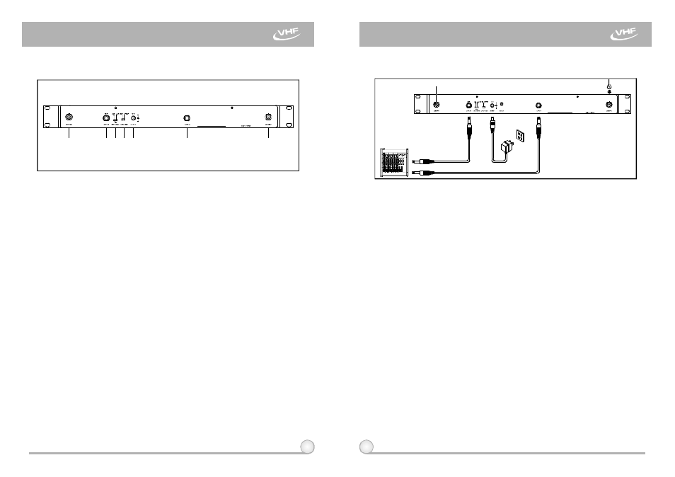
B. Rear Panel
(16)
(13)(14)(15)
(17)
(18)
(12)
3
4
(12)
Antenna B inputConnector: To install Antenna B.
(13)
Unbalanced Audio Output Jack B : 1/ 4
Phone Jack provides
unbalanced audio output signal from Channel B.
(14)
(15)
Unbalanced Mixed Switch
When switch to "MIXED", system will have
mixed AF output. AF signal from both Channel A & B will be exported
from "Output B" and no AF output from "Output A". When switch to
"Separate", AF signal will be exported separately from "Output A" and
"Output B".
(16)
DC Input Jack: To connect 12V DCfrom the AC/DC adapter.
(17)
Unbalanced Audio Output Jack A: 1/ 4
Phone Jack provides
unbalanced audio output signal from Channel A.
(18)
Antenna A Input Connector: To install Antenna A.
λ
﹕
λ
Unbalanced Level Switch: "0dB" selection is for "Microphone-level"
output. "+10dB" selection is for "AUX level" output.
-6dB
selection
is for halfof cable microphone volume.
〝
〞
1. Install two antennas, perpendicularly and fully extended, to the antenna
input connectors (12)&(18) at the rearpanel of the receiver, as shown in
Fig. 3.
2. Connect the AC/DC adapter cable to DC 12V INPUT JACK (16), then plug
the adapterunit into an appropriate AC outlet with caution to the correct
voltage under both AC outlet and adapter marked, as shown in Fig. 3.
3. AudioOutput Connection:
(a)
(b) Connection for Unbalanced Outputs: When the receiver is near the
input/output jacks of mixers/amplifiers, or both systemsuse phone
jacks, one c a n connect two (2) separate output cables to unbalanced
output jacks B(13) andA(17)in thereceiver. If output mode selector
(15) switches to "MIXED" mode, connect only one unbalanced cable to
unbalanced output jackB(13)as shown inFig. 3.
(c) Guitar Output: Using audio output cable attachedwith "PHONEPLUG"
type, plugone end fromthe unbalance-mixed output jackofareceiver,
and the other end to the input jack of a guitar amplifier. Switch the
Level Switch (14) to
position.
Unbalanced Level Switch (14) Setting Position: When connecting from
receiver'sunbalancedoutputto the "AUX-IN" jack o f a mixer or
amplifier o r "Electric Guitar", switch the Level Switch (14) to "+10dB"
position. Low sensitivity mayoccurif switch to the w rong level position.
When connecting fromreceiver's unbalanced output to the "MIC-IN"
jack o f a mixer or amplifier; switch the Level Switch (14) to "0dB"
position. Overload distortionmay occur if switchto thewronglevel
position. When using electric guitar,don't use "0dB" or "-6dB" position
as it may have generated insufficient level. Therearelots of amplifiers
for Karaoke machine intoday's market, however, gain of amplifier's
"MIC IN"is not unified. Therefore, if distortion is encountered,please
switch theLevel Switch (14)to "-6dB" position.
"+10dB"
2. INSTALLATION OF THE RECEIVER
Fig.3
Fig.2
DUAL CHANNEL WIRELESS RECEIVER
DUAL CHANNEL WIRELESS RECEIVER