Dual channel wireless receiver – MIPRO mr123da(2ce229) User Manual
Page 4
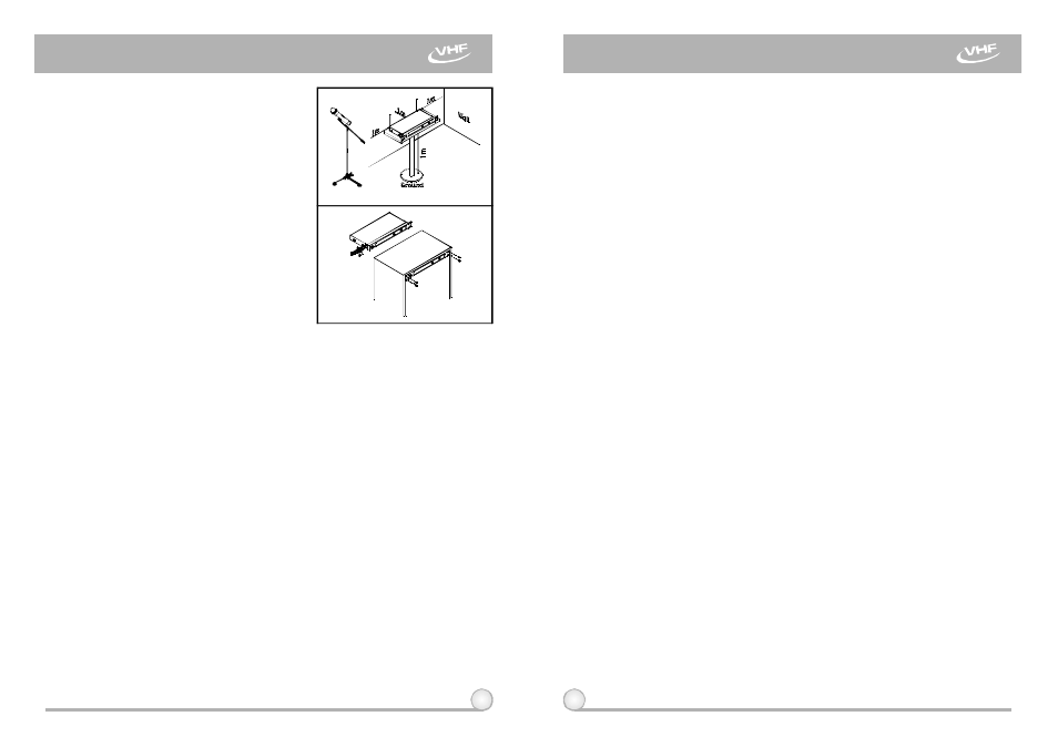
4.
Make sure the system performs correctly,
pleaseplace the system away from noise
sources. Place the receiver a t least 1
meter above the ground and away from
noise sources. Place the microphone at
least 1 meteraway from the receiving
antenna, a s shown in F ig. 4.
5.
With two rackmountbrackets installed,
receiver can be m ounted into anEIA
standard rackmount case, as shown in
Fig. 5. As an accessory, you may
purchase fromnearest dealer a front
antenna kit, which not onlyallowseasy
front antenna installation, but also
improves e fficiency of signal reception.
1.
Sets the volume of the mixer to its minimum before turning on the receiver
or transmitters. Then, turn on thereceiver. The moment when the receiver
is on, indicator on the front panelwill flash once to indicate the system is
normal.
2.
Sensitivity Adjustors (3)(10) allow receiver sensitivity adjustment and
"NOISE" indicators displaythe optimal adjustment. When neither
transmitters nor "NOISE" indicators turnon, it indicates the system is under
normalstandby status. When "NOISE" indicators (4)(9) turn on while
transmitters are off, the receiver is now under interference..
3.
If "NOISE" indicators (4)(9)turn on while transmitters are off, it indicates
the receiver is underinterferenceand the receiver will burstloud noises.
Under such circumstances, o n e can adjust sensitivity adjusters (3)(10),
conveniently located on the front panel,counterclockwise until "NOISE"
indicators (4)(9) turnoff toavoid unwanted loudnoise. However, if above
attempt should fail, the signal strength of interference is toostrongand
other frequencies must be selected to avoid interference. Turning sensitivity
adjusters (3)(10) counterclockwise w i l l reduce both receiver sensitivity and
receivingdistance; turning clockwise willincrease both sensitivity and
receivingdistance.
4.
Under normal circumstances, the RF SIGNAL LED indicators (5)(7) light up
and indicators of antenna A a nd B blink interchangeablely at regular path
when a microphone or transmitter is turned on near the receiver to indicate
the receiver is ready fornormal operation. Adjusts the volume of amplifier
to desired level and speak into the microphone where A UDIO LED
indicators (6)(8) will glow according t o t h e strength of sound level. Volume
of wireless microphone shouldbeadjusted directly from the amplifier. If no
LED glows or nosound outputs, the system is notfunction properly, thus it
must be checked.
5
6
1.
Since the installation of antenna influences the operatingefficiency of the
receiver, the most important rule is tominimize thedistance between
receiving antenna and microphone for betterreception and performance.
2.
The external DC powersupply should not fall under 12V, otherwise it would
not work properly. If it isover 15V, s ome components of the receiver will be
damaged.
3.
When using multi-channel systems s imultaneously,proper channel
frequency selection is very important to avoid mutual interference.
Fig.5
Fig.4
3. OPERATION INSTRUCTIONS
4. CAUTION
DUAL CHANNEL WIRELESS RECEIVER
DUAL CHANNEL WIRELESS RECEIVER