Wireless receiver – MIPRO mr801(2ce126)a2 User Manual
Page 2
Thank you for selecting MIPRO U H F h a l f 19-inch unit true diversity
wireless receiver system. Before operating please read this instruction
manual carefully a n d thoroughly inorder to attain the correct operating
procedures and achieve the best results.
This system is divided into UHF single channel true diversity
receiver with matching one microphones and individual volume controls.
This system is also equipped with "PILOTONE" and the latest "NOISE
LOCK" dual-squelch circuit, and provides the efficacy for eliminate the
random noise interference when the receiver is at standby state.
(Fig.1)
(1) Antenna Input Connector: For Front AntennaPlacement.
(2) Power Switch & Indicator: When switch is turned on, red indicator
illuminates to denote normal power status.
(3) RF Signal Indicator: Indicates receiving transmitting R F signals.
(4) Audio signal Indicator: Indicates the microphone signal.
(5) Antenna Input Connector: For Front AntennaPlacement of dual
channel.
(Fig.2)
WIRELESS RECEIVER
①
×
Audio Output Cable
1
③
×
Antenna
2
②
×
Instruction Manual
1
④
×
AC/DCAdapter
1 or PowerCable x 1
This system includes the following accessories:
A. Front Panel
1. Parts Name And Functions
- 2 -
- 1 -
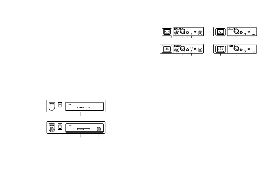
B. Rear Panel
(7)
UNBALANCEDOUT
BALANCEDOUT
L I N E
MIC
LEVEL
SQ
(Antenna in rear)
(8)
(10)
(9)
(13)
(12)
(11)
(Withswitching
(Antenna infront)
powersupply)
(6)
(Withswitching
powersupply)
(8)
(9) (10)
(13)
(12)
(11)
+
-
MIC
UNBALANCEDOUT
BALANCEDOUT
ANT.B
LINE
SQ
LEVEL
ANT.A
MIC
UNBALANCEDOUT
BALANCEDOUT
ANT.B
LINE
SQ
LEVEL
ANT.A
UNBALANCEDOUT
BALANCEDOUT
L I N E
MIC
LEVEL
SQ
(6)
(7)
(9) (10)
(12)
(11)
(10)
(9)
(12)
(11)
(6) AC Input Jack: Toconnect 85 ~ 265 Volts AC power.
(7) DC 12V Input Jack: To connect 12V DC from the AC/DC adapter.
(8) Antenna Input Connectors: For Rear Antenna Placement.
(9) Balanced Audio Output Jack: With Cannon / XLR type connector
provides balanced audio output signal f r o m this jack to the amplifier.
(10) UnbalancedAudio Output Jack: With 1/ 4" Phone Jack provides
audio output signal from this jack to the amplifier.
(11) Unbalanced Level Switch: "MIC" selection is for "Microphone-level"
output. "LINE" selection is for "Line-out" level output.
(12) Squelch Adjusters:Adjust the squelchlevel to eliminate the RF
noise interference at receiver stand-by state.
(13)Antenna Input Connectors: For rear Antenna Placement.
(Antenna in front)
(Antenna in rear)
(4)
(2)
POWER
(2)
(1)
(3)
(5)
POWER
(3)
(4)
SIGNAL
TRUEDIVERSITYWIRELESSRECEIVER
MR-801
AUDIO
ANT.B
TRUEDIVERSITYWIRELESSRECEIVER
MR-801
SIGNAL
AUDIO