Operation instructions – MIPRO mr801(2ce126)a2 User Manual
Page 4
1. Turn volumecontrols of the receiver and mixer in use to a minimum
setting before turn on the m icrophones or transmitters. After
switches o n t h e receiver, the power switch red indicator illuminates
to denote normal power status.
2. If SIGNAL LED indicators (3) o f t h e receiver light on before switches
on the microphone or transmitter, it indicates the receiver is receiving
interference signals. Thissystem has Pitlotone andNoiseLock dual-
squelch features and no noise output will occur. If multiple channels
are used and bothSIGNAL andAUDIO LEDs glow a n d interference
noise appear, simply adjust the Squelch controls (12) clockwiseuntil
AUDIO signal indicators to extinguish. (Fig. 10). However, by
adjusting the squelch controls, it affects the sensitivity level of the
receiver, therefore, shorten the operating distance and decreases the
stability.
4. Operation Instructions
(Fig.8)
(Fig.9)
(Fig.10)
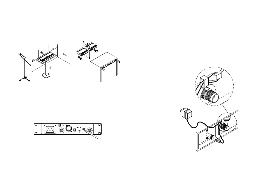
3. Make sure that the system performs correctly by placing the system
away from noise sources. Place the receiver at least 1 meter above
the ground andaway from noise sources. Place the microphone at
least 1 meter away from the receiving antenna, as shown in Fig. 8.
4. After completion, it can be rackmounted into an EIA standard rack
case, as shown in Fig. 9.
Ground
- 6 -
- 5 -
ANT.B
BALANCEDOUT
MIC
LINE
LEVEL
UNBALANCEDOUT
SQ
ANT.A
3. Under normal circumstances, the SIGNAL indicator lights up when a
microphone or transmitter is turned o n n ear the receiver to indicate
the receiver is ready for normal operation. Once sounds to the
microphone andthe AUDIO LED indicators (4) will glow according to
the strength ofsound level. If no LED glows or no sound outputs,
the system is not function p roperly, thus it must be checked.
4. The microphoneoutput level needs to beadjusted at the amplifier or
mixer. No need to adjust a t the receiver itself.
5. Plug the cable of the mains unit into dc socket on the receiver's
back panel. Thread the cable through the cable grip as shown on
the above illustration. The cable grip prevents the connector from
being pulled off by accident.
(Fig.11)