Handheld wireless microphone – MIPRO mr801(2ce126)a2 User Manual
Page 6
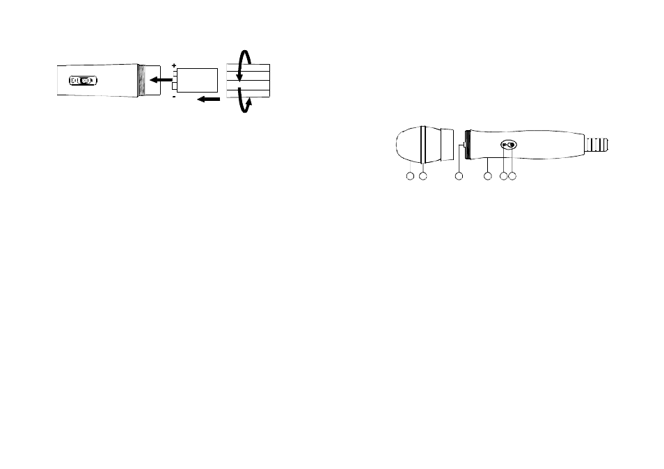
1. Unscrew battery cap in a counter-clockwise direction (8).
2. Insert a 9V battery into the battery compartment according to the
correct polarity as shown in Fig.2. The m o ment thebattery touches
the terminals, the indicator will flash briefly (8). This means the
polarity is correct. However, if no flashoccurs, this indicates wrong
insertion orthat the battery is dead. Please re-insert the battery
according to its correct polarity or exchange it for a fresh battery.
1.
When microphone is switched on:
When the power is switched on, the indicator will flash briefly
indicating normaloperation.
2.
Aftermicrophoneis switched on:
TheSIGNAL LEDindicator (3)on receiver glows. The more LEDs
thatglow indicatethat the received signal strengthis stronger. If
onlythe redLEDilluminates it indicates abnormal receiving status
andinsufficient signal strength.
3.
During Usage:
TheAUDIOLED indicator (4)on the receiverwill illuminateaccording
to theaudiosignalstrength from the microphone. When the redLED
is ON, it indicates that maximum sound pressure level has b e e n
reached but d o e s n o t represent d istortion.
4.
When the microphone is not in use:
Make sure that you turn off themicrophone after use to extendthe
battery life.Remove the battery from the battery compartment if
microphone is not t o be used again forsometime. If a rechargeable
battery wasused,take it o u t and recharge it.
(Fig.2)
- 9 -
2. Battery Insertion
3. Operating Instructions
HANDHELD WIRELESS MICROPHONE
- 1 0 -
(Fig.1)
This microphone utilizes advanced modular assembly and PLL
synthesized design. Preprogrammed with 30 frequencies allows the user
to freely select non-interference channels. Italso incorporates "Pilotone
& NoiseLock dual-squelch" to eliminate noise interference.
6
5
4
3
2
1
1. Grille: Protects cartridge and prevents " POP noise.
2. Rolling Proof Color Ring: For frequency differentiation and its
polygonal shape prevents microphone from rolling.
3. Battery Compartment: Designed to accommodate one piece 9V
battery.
4. Housing: Upper portion to be connected to capsule module and
battery. Internally, it holds transmitter PCB.
5. Battery Status Indicator: Indicates the power o n / off and battery
status. When power switch is turned ON, the red LEDs indicator
flashes briefly, indicating normal battery status. If no flash o ccurs, it
has either no battery or the battery is drained or installed incorrectly.
After power on and the indicator stays lighted. It warns the battery
is weak and a new battery replacement is thus necessary.
6. Power On-off Switch: Slide the switch for power "ON" or "OFF".
1. Parts Name And Functions