Setting phase current, Using the oscillator with switches & plcs, Run switch (closed=run) direction switch – Applied Motion PDO2035 User Manual
Page 11
!
Always unplug the line cord from the wall before attaching it
to the PDO 2035
-11-
12345
1000
500
250
125
HALF
STEP
Setting Phase Current
Before you turn on the power supply the first time, you need to set the driver for the
proper motor phase current. The rated current is usually printed on the motor label.
The PDO 2035 drive current is easy to set. If you wish, you can learn a simple
formula for setting current and never need the manual again. Or you can skip to the
table on the next page, find the current setting you want, and set the DIP switches
according to the picture.
Current Setting Formula
Locate the bank of DIP switches next to the motor connector. Four of the switches
have a value of current printed next to them, such as 500 and 1000. Each switch
controls the amount of current, in milliamperes (mA), that it's label indicates. There
is always a base current of 125 mA. To add to that, slide the appropriate switches
toward their labels. You may need your small screwdriver for this.
Example
Suppose you want to set the driver for 1.25 amps
per phase (1250 mA). You need the 125 mA base
current plus another 1000 and 125 mA.
1250 = 125 + 1000 +125
Slide the 125 and 1000 mA switches toward
the labels as shown in the figure.
Connecting the Motor
Never connect the motor to the driver when the AC power is on.
Secure any unused motor leads.
Never disconnect the motor while the AC power is on.
Never connect motor leads to ground or to a power supply.
You must now decide how to connect your motor to the drive.
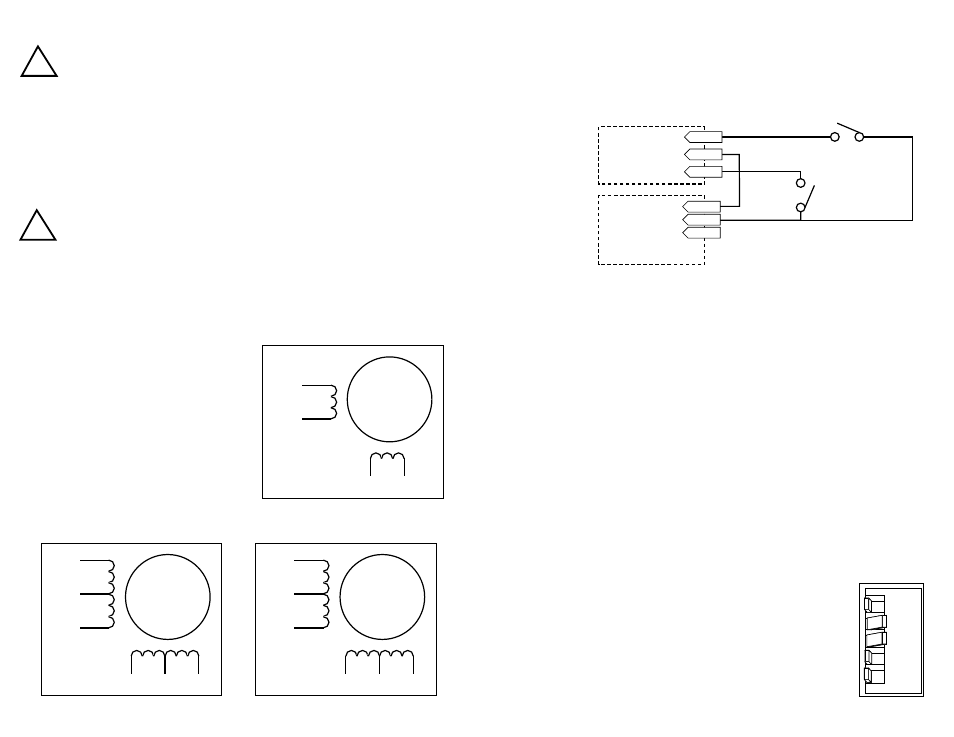
Four lead motors can only be connected
one way. Please follow the sketch at the
right.
Six lead motors can be connected in
series or center tap. In series mode, motors
produce more torque at low speeds, but
cannot run as fast as in the center tap
configuration. In series operation, the motor
should be operated at 30% less than the
rated current to prevent overheating.
Winding diagrams for both connection
methods are shown below. NC means not
connected.
A+
A–
B+
B–
4
lead
motor
Red
Blue
Yellow
White
4 Leads
A+
A–
NC
B+
B–
NC
6
lead
motor
Red
Black
Red/
Wht
Green
Grn/Wht
White
A+
A–
NC
B+
B–
NC
6
lead
motor
Grn/Wht
White
Green
Red
Red/
Wht
Black
6 Leads Series Connected
6 Leads Center Tap Connected
-6-
!
DIR
PDO 2035
5 position
connector
PDO 2035
4 position
connector
CW
CCW
WPR
COM
STEP
Using the Oscillator with Switches & PLCs.
If you plan to use the PDO 2035 in oscillator mode, you may need a source of
voltage to activate the optoisolation circuits. This is true if you are using
mechanical switches or relays. It may also be the case if you are using a PLC with
optically isolated outputs, since they behave like switches.
run switch
(closed=run)
direction switch
•Connect the black or brown wire to the PDO 2035 "L" terminal of the AC power
connector. That is the line, or "hot" connection.
•Connect the white or blue wire to neutral. That's the "N" terminal.
•Finally, and most importantly, connect the green wire to the GND terminal. That
connects the PDO 2035 metal enclosure and DC power supply ground to earth
ground.