Applied Motion PDO2035 User Manual
Page 4
-4-
You can also use an external analog voltage to set the speed. The voltage must be
between 0 and 5 VDC. Connect the voltage to the WPR pin and the voltage
return to CCW. For the LO speed range, the conversion is 240 steps/sec/volt. For
the HI speed range, the formula is 2400 steps/sec/volt.
If the analog voltage source generates it's own accel and decel ramps (such as a
servo controller) set the ACCEL and DECEL trimpots at the "no accel/decel" setting
so the oscillator does not interfere with the ramps.
-13-
cw
external
pot
Signal +
Signal -
Using Remote Speed Control Potentiometer
The PDO 2035 step motor driver includes an analog signal input connector that can
be used to control the oscillator speed externally. Normally, an on board
potentiometer controls the speed. Whether you use the on-board or external pots,
the accel/decel ramping remains active.
You will need:
• a 1k
Ω
- 10k
Ω
linear potentiometer. A multiturn type is recommended.
• a shielded, three wire cable
To install the external pot:
• locate the 5 position front panel connector (marked tach+, tach-, etc)
• prepare a cable with your pot on one end and the connector on the other end:
➤ the potentiometer wiper connects to the WPR terminal
➤ the potentiometer CW terminal connects to the CW terminal
➤ the third pot terminal connects to CCW
➤ the cable shield connects to the third pot terminal
With this arrangement, speed will increase as you turn the external pot clockwise.
The on board trimpots will still control acceleration and deceleration times.
Set the EXT/INT switch to EXT to select the external potentiometer.
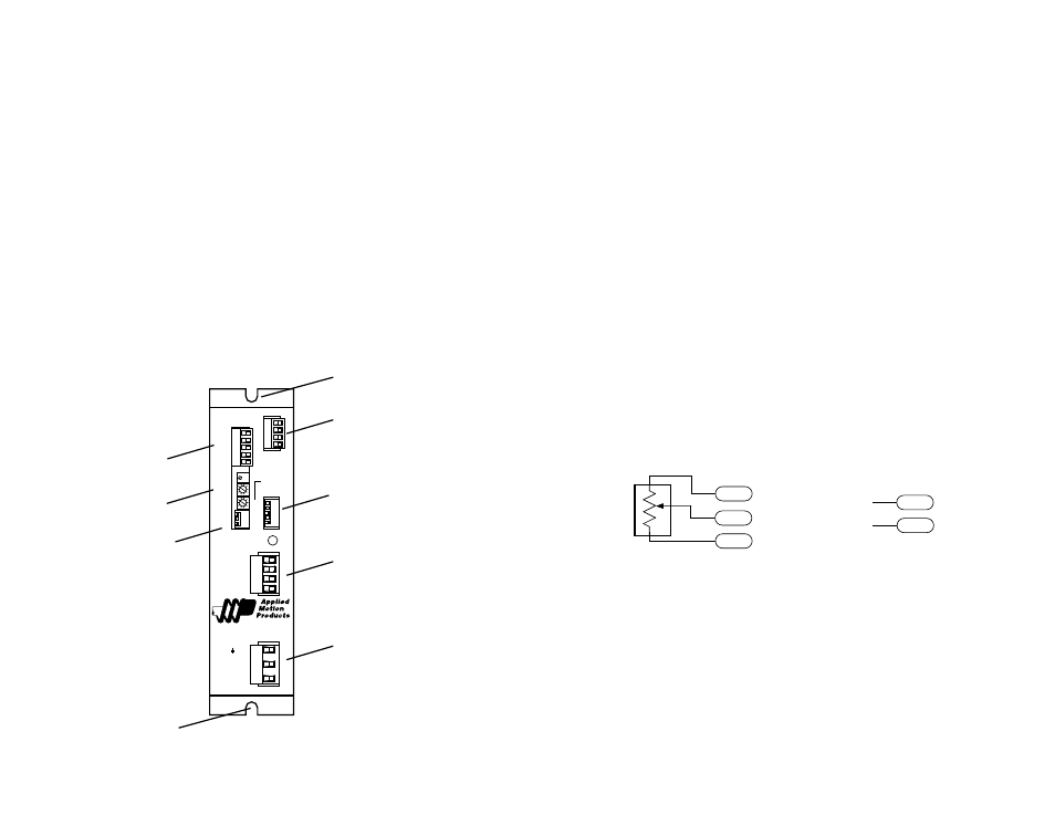
External Pot Connection
Analog Signal Connection
DIR
EN
COM
STEP
TACH+
TACH-
WPR
CCW
CW
123
12345
PDO 2035
Step Motor Driver
POWER
HALF
STEP
B–
B+
A–
A+
GND
N
L
HI
LO
➜
BYPASS
INT
➜➜
EXT
➜
➜
FULL
STEP
SPEED
DECEL
ACCEL
MOTOR
AC POWER
1000
500
250
125
CURRENT
(BASE = 125mA)
motor connector
switches
(current setting
full/half step)
signal connector
(step, dir, enable)
mounting hole
mounting hole
switches
(osc set up)
trimpots
(speed, accel, decel)
signal connector
(ext speed, tach out)
AC Power connector
Getting Started
To use your Applied Motion Products motor control, you will need the following:
• an AC power cord
• 5-24 volts DC to activate the optoisolation circuits
• a source of step pulses
• if your application calls for bidirectional rotation, you'll also need a direction
signal
• a compatible step motor (minimum inductance of 1 mH/phase)
• a small flat blade screwdriver (2.5 mm) for tightening the connectors and
adjusting the oscillator
• If your application calls for connection to 220 VAC, you will need a small Phillips
screwdriver in order to remove the drive cover.
Always disconnect AC power to the drive before removing the cover.
The sketch below shows where to find the important connection and adjustment
points. Please examine it now.
All mating connectors are included.
CW
WPR
CCW
WPR
CCW