Ab 3, Captive screw, Audio return channel (arc) steps – Atlona AT UHD SW 52 User Manual
Page 5: Connecting, Pin out color will differ per rs-232 cable, Black : - white, Power rs-232 clockwise counter clockwise, See picture 4)
5
atlona.com
Toll free: 1-877-536-3976
Local: 1-408-962-0515
Captive Screw
HDMI 1
HDMI 2
HDMI 3
HDMI 4
HDMI 5
VOLUME
AT-UHD-SW-52
R
+
+
-
-
L
FW
LAN
RS-232
RX TX
DC 5V
- +
HDMI IN
HDMI OUT
AUDIO
S/PDIF OUT
1
2
3
4
5
1
2
POWER
INPUT
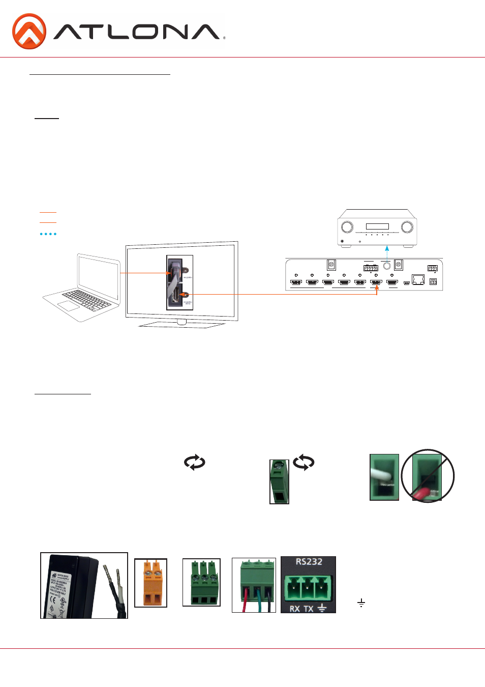
ARC enables a source connected to a display to route audio back to the switcher and send the de-embedded
audio out the S/PDIF output.
1. Check to be sure the display supports ARC
2. Enable ARC on HDMI output 1 of the switcher through RS-232 (command ARC on), TCP/IP, or webGUI
3. Connect HDMI output 1 of the switcher to the ARC labeled input port on the display
NOTE: The switcher must be connected to the display’s HDMI ARC input
Note: Works well with audio from ARC enabled “Smart” televisions
4. Connect the source to a non ARC HDMI input port on the display
5. Connect the S/PDIF port to an AVR or Zone Amp
Audio Return Channel (ARC)
Steps
HDMI
Bidirectional HDMI w/ARC signal
Audio loop-out
S/PDIF audio loop-out
Bidirectional HDMI ARC signal
HDMI
Connecting
Captive screw connectors are an added feature on the UHD-SW. The Captive screw connectors allow you to
cut cables down to a suitable length, reducing cable clutter while providing a more reliable connection.
The captive screw connectors have
a contact bar that is adjusted to
compress the wire against the top
contact plate. Use the screws at the
top of the connector to compress the
wire against the contact plate.
When connecting the cables to the female captive screw connector it is important that the wires be
terminated correctly. The female captive screw connector has a contact plate at the top and must have the
wires touching it for signal to pass. When wired correctly (see picture A) the signal will pass, incorrectly (see
picture B) no signal will pass.
The power cable (picture 1) will have exposed wires. Each wire is encased in a different colored cover. Female
captive screw connectors are included: Power (see picture 2) and RS-232 (see picture 3).
2
Power
RS-232
Clockwise
Counter
Clockwise
Turn the screws clockwise to
raise the contact bar to the
upper contact plate and hold
the wires in place.
Turn the screws counter
clockwise to lower the
contact bar to release the
wires.
A
B
3
RS-232 pin out will be
determined by the RS-232
cable and will connect as Rx
(receiver), Tx (transmitter),
and (ground).
(See picture 4)
Pin out color
will differ per
RS-232 cable.
4
Black: - White: +
- +
1