Rev. 1.00 – BIXOLON SRP-F310 User Manual
Page 24
Rev. 1.00
- 24 -
SRP-F310/312
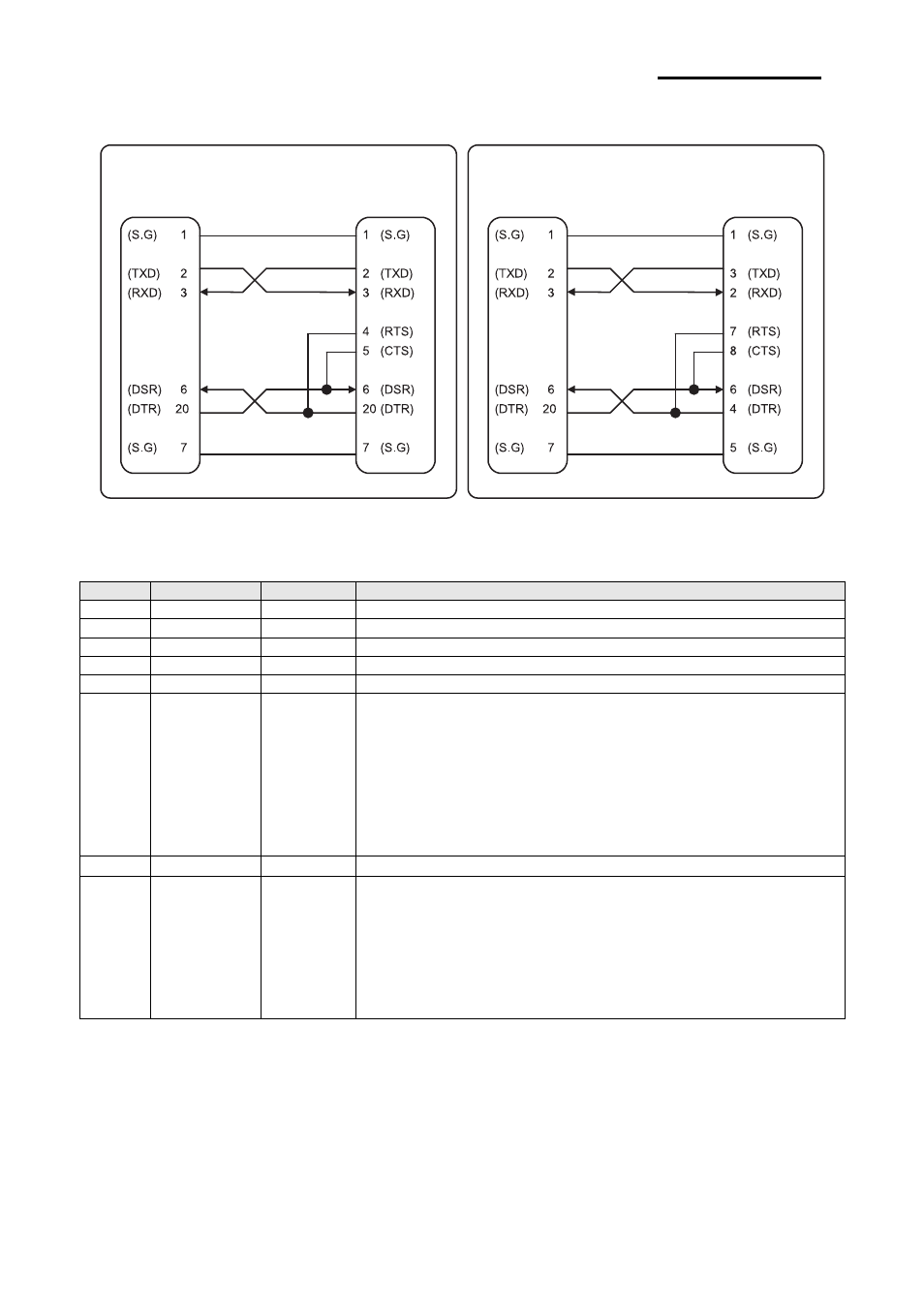
3-5-1(c) Cable Connection
Figure 3-7 RS-232C Cable Connection
3-5-1(d) Signal Description
Pin No.
Signal name
Direction
Function
1 FG -
Frame
Ground
2 TxD Output
Transmit
Data
3 RxD Input
Receive
Data
4 RTS Output
Ready
To
Send
5 CTS Input
Clear
To
Send
6 DSR Input
This signal indicates whether the host computer can receive data.
(H/W flow control)
1) MARK(Logic1): The host can receive a data.
2) SPACE(Logic0): The host can not receive a data.
3) The printer transmits a data to the host, after confirming
this signal.
4) When XON/XOFF flow control is selected, the printer does
not check this signal.
7 SG -
Signal Ground
20 DTR Output
This signal indicates whether the printer is busy. (H/W flow control)
1) MARK(Logic1): The printer is busy.
2) SPACE(Logic0): The printer is not busy.
3) The host transmits a data to the printer, after confirming
this signal.
4) When XON/XOFF flow control is selected, the host does
not check this signal.
Table 3-15 RS-232C Pin Description
PRINTER
SIDE (25P)
HOST
SIDE (25P)
PRINTER
SIDE (25P)
HOST
SIDE (9P)