3-4 i/f pba detect block diagram, 3-5 rs-232c communication block diagram, 42 4-3-5 rs-232c communication block diagram – BIXOLON SRP-F310 User Manual
Page 42: Rev. 1.00
Advertising
Rev. 1.00
- 42 -
SRP-F310/312
4-3-4 I/F PBA Detect Block Diagram
When the printer is ON, the printer checks what kind of the I/F PBA is installed. After detection, the CPU
specify the I/O port properly. The following is the method of I/F PBA detection.
The I/F PBA has the three return Signal (MD0~2).
The CPU recognize the I/F PBA by the value of the three return signal.
I/F PBA
MD0
MD1
MD2
RS-232C
L H L
IEEE1284 H
L
L
No
Connection
L L L
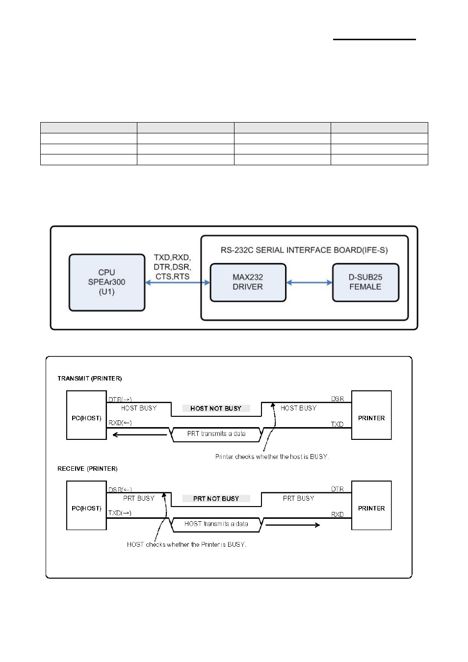
4-3-5 RS-232C Communication Block Diagram
The CPU is used for serial communication. And also RS-232C Driver (MAX232), is used to serial
communication. Show following block diagram.
[Figure 4-8 RS-232C Communication Block Diagram]
[Figure 4-9 RS-232C Communication Waveform]
Advertising