Casella CEL CEL-206 User Manual
Page 8
Casella USA
17 Old Nashua Rd #15
Amherst, NH 03031 USA
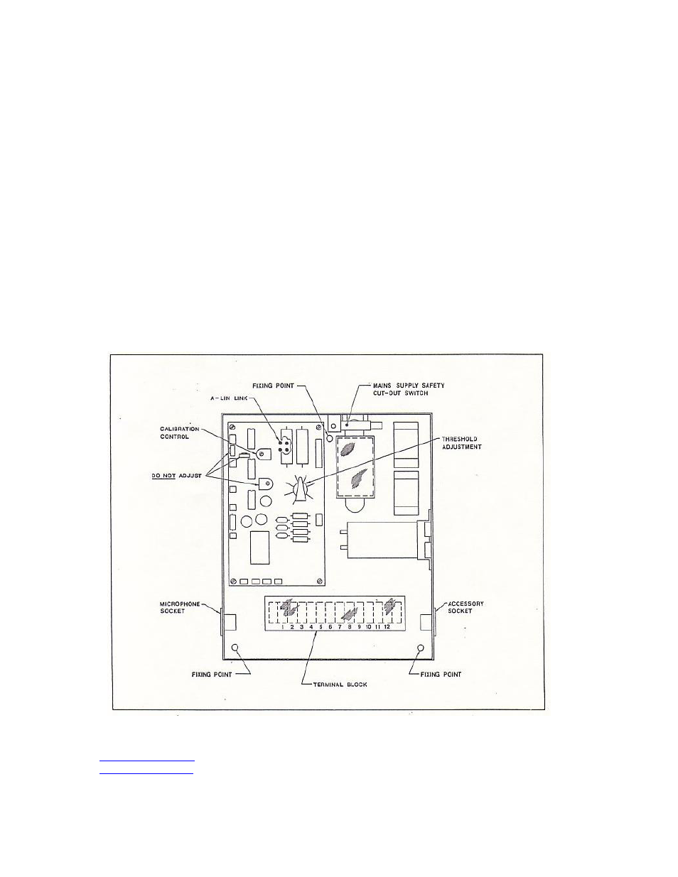
Any drift in the instrument's setting due to environmental influences, etc, may
be compensated for by adjustment of the calibration control that is located on
the main printed circuit panel. As there are four preset potentiometers on this
panel care must be taken to ensure that the correct one is adjusted. The higher
one is the calibration potentiometer (see Fig 1), whilst the lacer ones are the
detector bias setting which must not be altered. As the systems must be
operational to perform the calibration it is necessary to override the mains
safety cut-out system. This is achieved by removing the central locking screw
from the front panel and replacing it into its thread with the cover open.
To set the threshold level the front cover must be opened, the required level
set on the threshold control (see Fig 1) and the cover closed again. Having
completed the calibration and setting of the device a security seal should be
wired through the holes in the main chassis and front cover to ensure the
device is not tampered with.
CEL-206 Internal controls and layout
Page 8 of 16
Tel: (800) 366-2966
www.casellausa.com
2 Mar 2009
Fax: (603) 672-8053