Installation – Casella CEL Multimet User Manual
Page 6
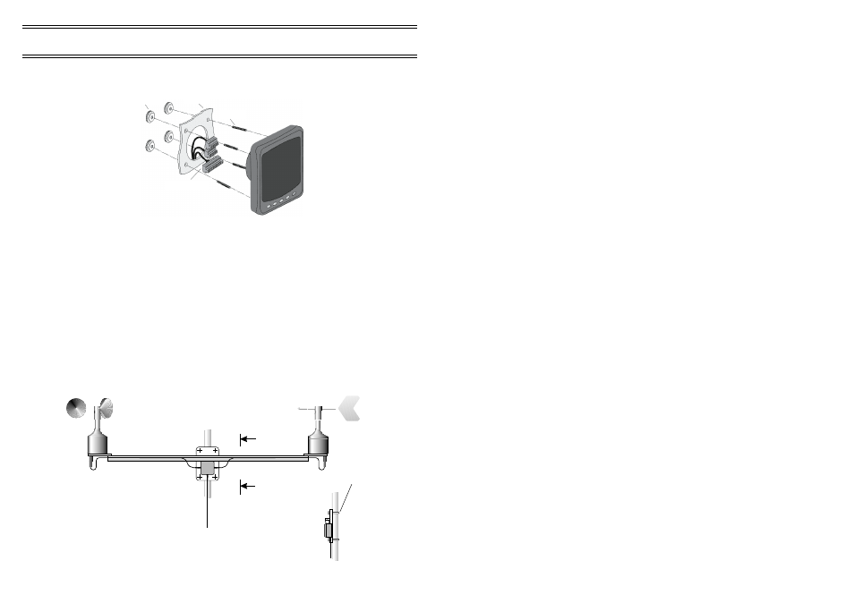
Screw the studs into the rear of the instrument and secure to the
panel using the supplied thumb nuts. A cable loom is supplied for the
interconnection of sensors, power supply and communication cables.
¤
Try to keep cable runs as short as possible to reduce the risk of
voltage drops and interference.
¤
Protect all exposed or buried cables from physical damage.
¤
Cable installation and connection to mains power should be
performed
in accordance with local safety guidelines and legislation.
1.2.2 Sensor Installation and Wiring
The combined wind speed and direction sensor should be located in an
exposed location free from sheltering effects or sources of air turbulence.
Guidance from Meteorological agencies typically recommends a
measurement height of 10 m in a flat area, free from large buildings or trees
within a 300 m radius.
Installations in industrial or urban environments will experience
increased turbulence and a compromise in location may be inevitable. Try to
select a location representative of the wind you wish to measure.
Installation
Thumbnuts
Bulkhead
M4 Studs
Cables & Connectors
02070
Wind Speed
Sensor
Terminal Box
View on A - A
"U" bolts
Up to 50 mm
diameter mast
Wind Direction
Sensor
02072
Maximum distance available
200 m with RS 232
Data Transmission Cable.
Wind Speed and Direction
Sensing Head 142000D
A
A
Page 6 of 16
MULTIMET Wind Speed and Direction System
& OnlinePro Software - Users Handbook